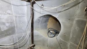
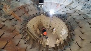
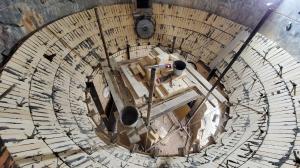
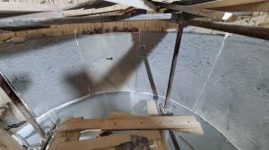
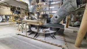
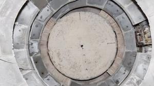
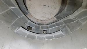
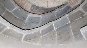
On August 20, 2022, Wellons.RU LLC completed the project fot the refractory lining replacement at the gypsum boiler. These works were carried out under the terms of the EPC contract, including engineering, selection and supply of materials, as well as work on tearing down the existing (old) lining. The lining works on the installation of a new refractory of the boiler, as well as dismantling and installation works of the main and auxiliary mechanical equipment (drive paddle mixers, feeders, gas ducts, etc.).
ENGINEERING.
When implementing the lining replacement project, it was necessary to solve two main tasks:
1. Selection of refractory products – the existing original lining has served for ~ 40 years, in fact, since the installation of this boiler, and the main task for the selection of refractory linings was the task of finding analogues of refractory and heat-insulating products from PLIBRICO, which currently does not exist. The specialists of Wellons.RU LLC selected refractory and heat-insulating materials based on the available data of the original project. Moreover, the refractory of the working layer, in agreement with the customer, was replaced with refractory concrete with higher strength characteristics and heat resistance. Due to the fact that the design of the lining has proven itself from the best side (long service life), we, at the request of the customer, have retained the original design of the lining - two-layer lining, the main heat-insulating layer is heat-insulating brick, the working layer is monolithic refractory concrete.
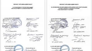
2. Dismantling and installation of mechanical equipment - the second, and in importance the first, task was to resolve the issue of dismantling the gypsum boiler with all the main and auxiliary equipment located on the lid of the gypsum boiler (blade mixer drive, gas duct feeders and other equipment). To solve these problems, Wellons.RU specialists developed the appropriate plan of organization of work (POW) for the dismantling / assembly work of mechanical equipment, as well as the POW for refractory breaking and lining work.
EQUIPMENT DISMANTLING.
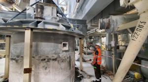
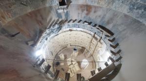
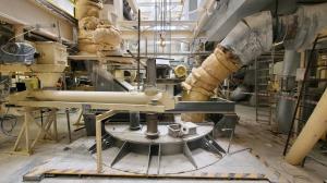
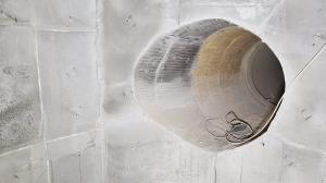
Within the framework of this project (EPC contract), the dismantling of the mechanical equipment located on the lid of the gypsum boiler was carried out to lift the gypsum boiler from the boiler body, respectively. The need for these works is due to the design of the protective refractory lining of the boiler and directly to the location of the gypsum cooker. The distance between the wall of the gypsum tank and the refractory lining is 335 mm, and between the wall of the tank and the shell of the boiler body is 585 mm. This distance does not allow work on breaking out the existing lining and, moreover, work on the installation of a heat-insulating layer and work on the device formwork and pouring refractory monolithic concrete of the working layer. Due to the presence of these limitations, the project provided for the dismantling of mechanical equipment located on the lid of the gypsum boiler, namely: the paddle mixer drive including the drive motor, screw feeders, gas ducts with heat-insulating sheathing, instrumentation equipment and other boiler piping. Unfortunately, in the process of dismantling, it turned out that without a huge risk of damage to the main drive coupling half and the paddle agitator drive shaft, it is not possible to dismantle the frame of the gearbox and the electric motor. As a result, a decision was made to lift the complete boiler brewing vessel, with the paddle agitator drive frame. This, in turn, did not allow to extend the cooking vessel to its full height and free up the internal space of the boiler by 100%, due to the limitation of the lifting height due to the existing equipment of the gypsum-cooking line. The lift was limited by the screw conveyor of the bag filter of this technological line of the boiler - the remaining height of the tank in the boiler was 780 mm. After examining the technical condition of the existing lining of the upper chord of the boiler, together with the specialists of the plant, it was decided to leave the existing lining (lining of the upper chord), due to its normal technical condition.
In the process of dismantling, a number of additional activities were carried out that were not provided for by the project, due to the lack of detailed technical documentation at the stage of developing the work organization project and, accordingly, at the stage of developing the network work schedule for this project.
The parallel organization of work on breaking out the existing refractory made it possible to stay within the general time frame for the implementation of this project, and compensated for the additional time spent at the stage of dismantling.
REFRACTORY TEARING DOWN.
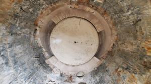
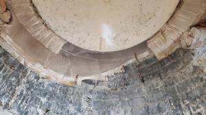
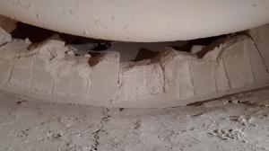
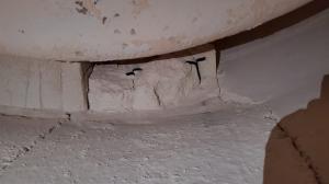
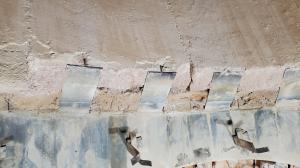
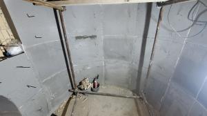
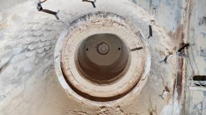
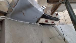
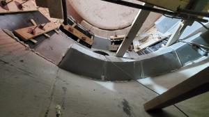
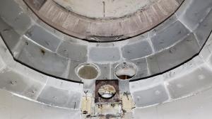
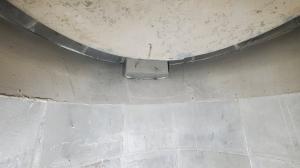
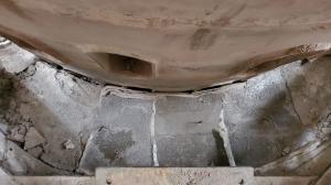
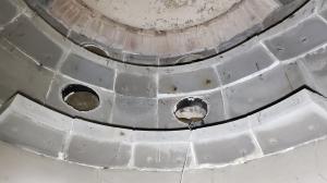
The technical inspection of the lining confirmed the correctness of the decision to replace the lining of the boiler furnace. After cleaning the boiler, including the removal of a thin layer of gypsum from the walls of the refractory, the following main defects were found, affecting, among other things, the efficiency of the boiler. Significant collapses of the guide "teeth" of the gas flow were found, as well as large, deep chips and a significant number of open deep cracks in the refractory lining. Part of the anchor products was exposed, as well as supports (supporting devices), which characterizes significant wear of the refractory of the working layer. Further impact on the exposed parts of the anchor products would inevitably lead to their burnout and further destruction of the refractory in the areas of supports and anchor products.
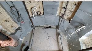
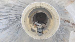
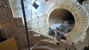
The refractory lining of the transition gas flue from the burner to the cylindrical part of the boiler was repeatedly repaired, the upper part of the flue had a significant sag and opening of the lining made of refractory heat-insulating bricks. Some of the photographs shown in this section show the defects described.
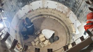
As mentioned earlier, in order to maintain the work schedule, due to the need for additional work related to the dismantling of mechanical equipment and lifting the brewing vessel from the boiler, it was decided to parallel break out the refractory of the lower cylindrical part of the boiler. The most detailed dismantling of mechanical equipment and breaking out of refractory are shown in the video “GYPSUM BOILER. DISMANTLING WORKS".
LINING WORKS.
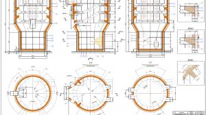
The implementation of this project was carried out under the terms of the EPC contract. To do this, the specialists of Wellons.RU LLC developed their own project for laying refractory lining (a set of working documentation) based on the drawing of the lining from the manufacturer's plant No. 1-21-030 "Installation for gypsum cooking - refractory lining"; selected heat-insulating and refractory materials; design and manufacture of anchor products; all works (mechanical and lining works) were within the scope of responsibility of Wellons.RU LLC. The main features of the work are shown in the relevant sections of this report below.
1. WALL LINING OF THE LOWER CYLINDRICAL PART OF THE BOILER:
The main lining consists of three layers: heat-insulating rolled material Cerablanket-128, 19 mm thick, heat-insulating refractory aluminosilicate bricks ShT-0.7, 124 mm thick. and a working layer of monolithic refractory concrete BORTCAST-50W, layer thickness 135 mm. The total thickness of the lining layer is 280 mm.
Wall lining arrangements:
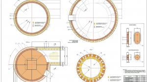
Before laying the main lining, a rolled heat-insulating material 19 mm thick is installed. (Cerablanket-128 (9760x610x19 mm)) in one layer over the entire surface of the metal structure of the boiler body - the lower cylindrical part. This material compensates for various thermal expansions of steel and refractory materials, thereby reducing the internal stresses that arise in the lining during its heating and operation. Due to the low values of the thermal conductivity of this material, its use allows to reduce the external temperature of the boiler shell. Installation of roll material is carried out in stages. After gluing the rolled heat-insulating layer (including on the bottom of the boiler), the laying of the heat-insulating layer from refractory heat-insulating bricks begins. Bricks of two formats are used - straight and shaped (double-sided ribbed wedge) - to ensure the correct circumference of the lining in accordance with the diameter of the shell of the boiler body. Brick laying is carried out according to the brick layout shown on the corresponding project drawing (No. W.RU 01-02). Layer thickness 124 mm. Brick laying is carried out using a masonry mortar based on aluminosilicate mortar.
ПIn parallel with raising the masonry, heat-resistant anchors are installed. In places where anchors are to be installed, cuts are made in place in the heat-insulating blanket. Anchors are installed according to the project documentation
The lining of the working layer is made of monolithic refractory concrete BORTCAST-50W. Refractory concrete is poured into pre-installed formwork. An immersion vibrator is used to compact the concrete mass. After the concrete has set, the formwork cards are dismantled. Expansion joints are made by installing rolled material on the side surfaces of the cards.
2. BOILER FURNACE LINING:
The main lining consists of three layers: heat-insulating rolled material Cerablanket-128, 19 mm thick, heat-insulating refractory aluminosilicate bricks ШТ-0.7, 114 mm thick. and a working layer of refractory heat-insulating brick ShTU-1.0, layer thickness 124 mm. The total thickness of the lining layer is 260 mm.
Before laying the main lining, a rolled heat-insulating material 19 mm thick is installed. (Cerablanket-128) in one layer over the entire surface of the metal structure of the gas duct. This material compensates for various thermal expansions of steel and refractory materials, thereby reducing the internal stresses that arise in the lining during its heating and operation.
As the main heat-insulating layer, heat-insulating bricks are used - to ensure the most correct circumference of the lining, in accordance with the diameter of the transition gas duct, bricks of two formats are used - a double-sided ribbed wedge. Brick laying is carried out according to the brick layout shown in the drawing No. W.RU 01-02. Layer thickness 114 mm. Brick laying is carried out using a masonry mortar based on aluminosilicate mortar. Brick laying is carried out in rings. In the upper arched part of the has duct, a removable supporting formwork (circle) is used. After the installation of the castle brick, the formwork is removed and moved to the next row.
Laying of the working layer is carried out with the use of refractory heat-insulating shaped bricks ShTU-1.0 - double-sided ribbed wedge, to ensure the most correct circumference of the lining. Layer thickness 125 mm. Brick laying technology is similar to the procedure described above.
The transition section of the gas duct to the lower cylindrical part of the boiler - the working layer of the lining is made of monolithic refractory concrete (BORTCAST-50W). Filling is carried out with cards with pre-installed anchors and a layer of rolled heat-insulating material, according to drawings No. W.RU 01-01 and No. W.RU 01-02. As the main heat-insulating layer, the pairing of heat-insulating layers of the vertical part of the boiler and the horizontal section of the flue is used.
3. LINING OF THE WALLS OF THE TRANSITION CONE OF THE CYLINDRICAL PART OF THE BOILER:
The main lining consists of: heat-insulating rolled material Cerablanket-128, 19 mm thick, heat-insulating bricks ШТ-0.7, 124 mm thick. and a working layer of monolithic refractory concrete BORTCAST-50W, layer thickness 135 mm.
In this area, an additional row of calipers was installed in the upper part of the cone. These calipers provide a reduction in the load from the lining of the upper cylindrical part of the boiler to the lining of the conical part. Moreover, the lower row of calipers is installed at an angle of 90° to the inclined surface of the shell of the transition cone, which in turn makes it possible to reduce the pressure forces of the lining on the upper edge of the lining of the walls of the lower cylindrical part of the boiler, acting tangentially. The lower row of calipers was left, due to their good technical condition (no traces of thermal impact).
Also, two additional rows of anchors were installed in order to additionally hold the denser and, accordingly, heavier lining and reduce the pressure of the lining of the inclined section on the vertical walls of the lower cylindrical part of the boiler. Work on the installation of the anchor field, on the installation of rolled heat-insulating material is similar to the procedure described above
When lining the heat-insulating layer of the transition cone, heat-insulating bricks ShT-0.7 of two styles are used - a straight brick and a double-sided ribbed wedge. The bricks are adjusted by sawing or the joints of the segments are filled with heat-insulating concrete BORTHERM-0.8 (density no more than 800 kg/m3), which has the same characteristics as heat-insulating bricks. These measures are applied when necessary.
Laying of the working layer is made of refractory concrete BORTCAST-50W. Refractory concrete is poured into pre-installed formwork. An immersion vibrator is used to compact the concrete mass. After the concrete has set, the formwork cards are dismantled. Expansion joints are made by installing rolled material on the side surfaces of the cards.
4. LINING OF THE WALLS OF THE UPPER CYLINDRICAL PART OF THE BOILER:
The main lining consists of two layers: heat-insulating refractory aluminosilicate brick ShT-0.7 with a thickness of 124 mm. and a working layer of monolithic refractory concrete BORTCAST-50W, layer thickness 125 mm. The total thickness of the lining layer is 250 mm. The device for lining the working layer in this zone is complicated by the presence of inclined guides of complex shape, which ensure the flow of the gas flow through the flame tubes of the cooking vessel. The thickness of these guides/teeth is 460 mm (excluding thermal insulation layer).
When lining the heat-insulating layer of the transition cone, heat-insulating bricks ShT-0.7 of two styles are used - a straight brick and a double-sided ribbed wedge.
Anchor products are installed according to the project drawings. For lining the walls of straight vertical sections, a heat-resistant anchor 4x30x200 mm is used, and in places where guide elements / teeth are installed, a heat-resistant anchor 4x30x400 mm is used. All anchor products are made of heat-resistant sheet steel AISI 310S (20X23H18).
After the installation of the heat-insulating layer and the installation of the anchor field, the formwork of the teeth of the lower chord is installed and they are poured with refractory concrete.
The second stage is the installation of the formwork of the "straight" vertical section above the previously cast segments of the guides of the first tier.
After setting the concrete and dismantling the formwork of the straight vertical part, the formwork of the horizontal segments of the second tier and the inclined segments between the first and second tier is installed. The formwork must retain the inner diameter of the lining, according to the drawing for the installation of the brewing vessel in further stages.
Filling of all subsequent cards is carried out only after the installation of all expansion joints using rolled heat-insulating material 13 mm thick.
Further lining of the walls of the upper cylindrical part of the boiler is repeated according to the above procedure.
The pouring of cards and segments of inclined and horizontal guides / teeth is carried out in a checkerboard pattern in order to achieve the maximum possible volume of refractory concrete laying.
This procedure is necessary in order to ensure the scope of work for the next shift, i.e. to ensure maximum employment of the brigade with minimum downtime. The process of concrete hardening takes quite a long time (at least 12-14 hours) and the work is organized in such a way that the working day is completely occupied with the dismantling of the formwork, its manufacture and installation, as well as pouring the prepared lining cards. To do this, under the formwork and pouring of the cards, all possible free, at a given time, sections of the lining for pouring are selected.
When forming maps around the cleaning nozzles / valves (opposite the flame tubes of the brewing vessel), the metal surface of the nozzles must be pasted over with a rolled heat-insulating material 13 mm thick.
The filling of the map around the emergency discharge chute (refractory concrete) is carried out last, due to the need to lower the brewing vessel into the boiler and attach the emergency discharge chute flange directly to the brewing vessel flange. Only after carrying out these measures, as well as checking the operation of the pneumatic relief valve (ensuring the alignment of the valve with the saddle of the brewing vessel flange), this card is poured into a pre-installed formwork. Concrete is poured through the upper cleaning nozzles of the boiler. After the end of the hardening processes, the formwork is dismantled.
It was found that in the process of lifting the brewing vessel from the boiler, the two upper segments of the guides of the upper chord were destroyed (the section of the gas flow exit from the boiler into the flue). This section was restored - anchor products were installed, formwork was installed and concrete was poured with expansion joints.
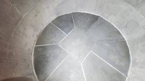
5. BOILER BOTTOM LINING:
The main lining consists of three layers: heat-insulating rolled material 19 mm thick. (Cerablanket-128), heat-insulating refractory aluminosilicate brick SHT-0.7 with a thickness of 124 mm. and a working layer of monolithic refractory concrete BORTCAST-50W, layer thickness 135 mm. The total thickness of the lining layer is 280 mm.
Before laying the main lining, it is necessary to install a rolled thermal insulation material 19 mm thick. (Cerablanket128) in one layer over the entire surface of the bottom of the boiler.
The laying of the heat-insulating layer is carried out using heat-insulating bricks. For laying the heat-insulating layer, a straight brick SHT-0.7 No. 8 (250x124x65) is used. Brick laying is carried out in one layer per edge. Layer thickness 125 mm. Brick laying is carried out using a masonry mortar based on aluminosilicate mortar.
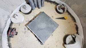
The lining of the working layer is made of monolithic refractory concrete BORTCAST-50W. Refractory concrete is poured into pre-installed formwork. First of all, the central card of the lining of the bottom of the boiler is installed. After pouring it and removing the formwork, radial maps are formed. The formwork is installed according to the concrete maps of the working layer shown in the drawing No. W.RU 01-02, on every second map in a row (in a checkerboard pattern).
The pre-prepared concrete mass BORTCAST-50W is poured into the formwork. An immersion vibrator is used to compact the concrete mass.
After the concrete of the poured cards has set (4 pcs.), the formwork partitions (dividing the mass of concrete according to the cards) are dismantled, and after the installation of expansion joints, the remaining cards are poured with concrete of the working layer.
6. LINING OF THE TECHNOLOGICAL HATCH AND PLUGS FOR CLEANING VALVES:
In the process of repair work, the lining of the technological door was replaced. The existing anchors (good technical condition) were used in the installation of a new lining. Before laying the concrete of the working layer, a layer of roll thermal insulation 40 mm thick was laid (two layers of Cerablanket-128, 19 mm each), and a layer 13 mm thick was laid along the perimeter of the door rib, as an expansion joint to compensate for thermal expansions of concrete and steel. Heat-insulating concrete BORTHERM-0.8 was laid as the concrete of the working layer.
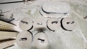
To make it easier to seal the nozzles of the cleaning valves, at the request of the service personnel, we made plugs from lightweight heat-insulating concrete. Their use will make it possible to speed up and facilitate the laying of cleaning pipes after carrying out the necessary work to inspect the flame tubes and clean them, if necessary. The plugs are installed in place and sealed with a rolled heat-insulating material 13 mm thick. External hatches are closed, the technological hatch door is hung in place.
INSTALLATION OF EQUIPMENT.
The main difficulty of the installation was to lower the brewing vessel to the design position, due to the fact that the gap between the brewing vessel wall and the guide segments / teeth was no more than 15-20 mm per side. Therefore, this lowering process must be as accurate as possible to prevent tank skew and possible destruction of the new refractory of the teeth/guide segments of the gas flow. To ensure the maximum possible verticality of the axis when lowering the container, an additional manual hoist was used. With the help of this auxiliary hoist, the correspondence of the vertical and horizontal axes was achieved when the brewing vessel was lowered into the boiler, preventing a possible distortion of the brewing vessel. After the brewing vessel was in the design position, the flange connection of the boiler cover was fixed with bolted connections using a wrench.
After that, all previously dismantled equipment was installed in the design position. Protective thermal insulation was installed on the boiler flues. The equipment was handed over for further piping and installation of instrumentation and equipment and commissioning of the equipment.
The lining work and installation of mechanical equipment are shown in the most detailed way in the video “GYPSUM BOILER. LINING WORKS. MOUNTING.".
PHOTO REPORT OF COMPLETED WORKS.
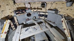
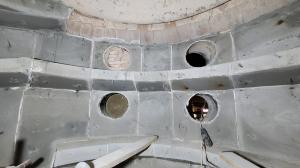
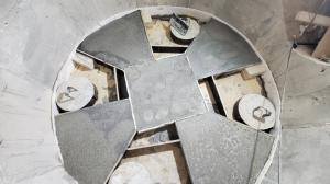
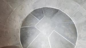
All photos presented in this report, as well as photos not included in this report and videos of the work performed, were transferred to the customer. Some of the final photos of the work performed are presented below:
PROJECT SUMMARY:
The project of replacing the lining of the gypsum boiler actually turned out to be very difficult, primarily due to the need to carry out work related to the dismantling / installation of equipment and the presence of restrictions on lifting mechanisms. At this stage, a significant amount of additional mechanical work was identified, which was not taken into account either by the cost estimate or by the equipment repair schedule. A feature of lining work is the need to manufacture complex formwork for gas flow guide segments, both horizontal and inclined sections, while maintaining the inner diameter of the boiler guide segments. Despite the difficulties that arose during the implementation of the project, due to the use of highly qualified liners and installers, as well as the help of the plant's specialists in solving organizational issues, all this made it possible to implement this project in 23 days(!), including all works (dismantling / installation of mechanical equipment; breaking out of the existing refractory and laying a new one).
