On August 29, 2020, Wellons.RU LLC successfully completed a project to replace the refractory lining of hot water boiler No. 1 (KTVm-5000) of the FM-Sever LLC boiler house. These works were carried out on the terms of an EPC contract, including engineering, selection and supply of materials, as well as works on breaking the existing (old) lining and lining works to install a new refractory lining of the boiler.
ENGINEERING.

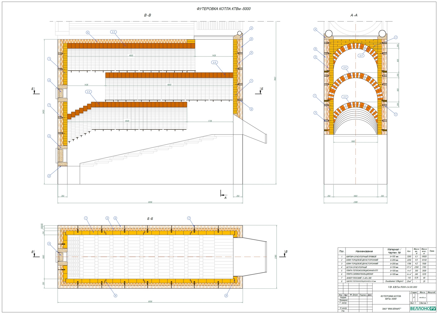
Due to the fact that this project is an analogue of the project carried out by the specialists of Wellons.RU LLC in 2019 on a hot water boiler No. 2, a working draft of a refractory lining was used with minimal changes. The design of the refractory lining remained unchanged - a two-layer heat-insulating lining and a working layer lining with the use of refractory bricks. In connection with the successful experience of operating the boiler lining No. 2 (completed earlier), as well as with the clarification of the geometric dimensions of the boiler furnace, the thickness of the heat-insulating layer decreased by 50 mm, to the thickness of the heat-insulating layer of 150 mm. Accordingly, the geometric dimensions of the furnace vaults were revised and the layout of the shaped refractory was brought to the actual dimensions.
REMOVAL OF REFRACTORY.


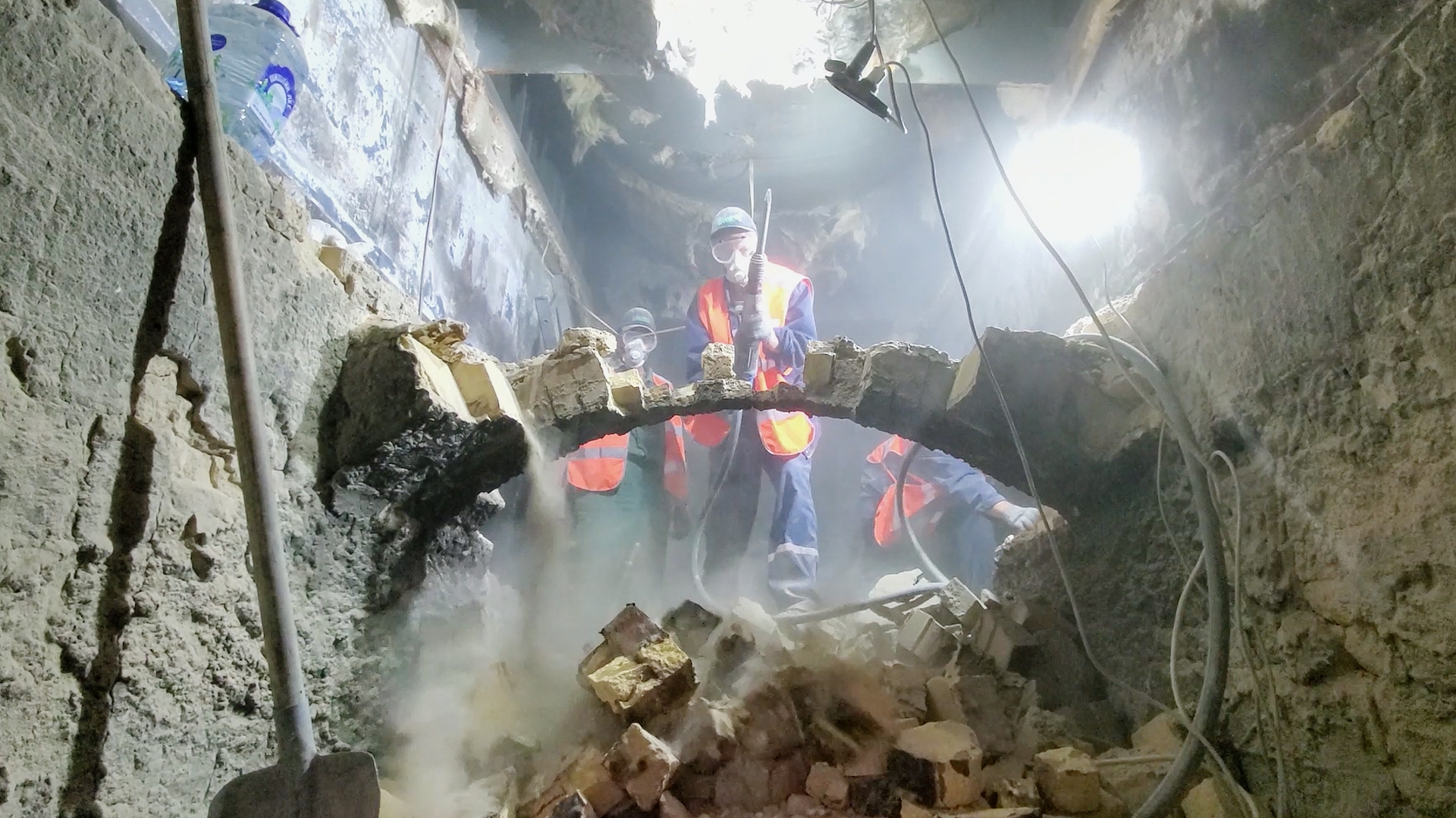
Within the framework of this project (EPC contract), work was carried out to break the existing refractory. Particular attention, in the process of breaking the refractory, must be paid to organizational measures to ensure the safety of the work performed, especially work related to the dismantling of vaulted structures, and the lower vault, in particular. The lower vault was made of brick with a thickness of 114 mm, had a large opening of the vaulted segments, and had a low structural strength.
The refractory lining was broken from top to bottom using a pneumatic jackhammer, with manual removal of the broken refractory through the upper and lower technological hatches and moving the refractory scrap into a container at a distance of up to 25-30 m. movement and disposal of industrial waste. Refractory removal / breaking work, with a total weight of ~ 35 tons, was completed in two and a half shifts (~ 30 hours). These works are shown in maximum detail in the video STEP I: REMOVAL OF THE FIREPROOF on our website.
LINING (REFRACTORY) WORKS.
All work related to the arrangement of the refractory lining, such as: breaking the refractory, assembling the refractory, the necessary auxiliary work (manufacturing of formwork, tooling and other works) are presented in our short video reports on the company's website in the section «REPLACEMENT OF THE Lining of BOILER No. 1 KTVm-5000». The main features of the work are shown in the relevant sections of this report below.
1. ZONE OF THE FIRST VALVE, GRID ZONE OF THE BOILER HEATER.


LINING OF VERTICAL WALLS – two layers of thermal insulation: from a kaolin board 50 mm thick and a calcium silicate board 100 mm thick; working layer - from refractory brick ША-I №9, thickness 150 mm. and special drawing items for fixing the anchor on the basis of ША-I №9. Total lining thickness 300 mm.
Wall lining ARRAGMENTS:
- The construction of the thermal insulation layer is carried out using one calcium silicate board (100 mm thick) and one kaolin board (50 mm thick). Plates are installed on the edge and pressed tightly against each other. The laying of the working layer of brick provides a strong and reliable fastening of these slabs. The structural strength of the plates (they do not crumble during operation) does not require additional fastening to their own anchors or to refractory glue.
- Bricklaying of vertical walls is carried out with panels, ~ 1500 mm wide, with the formation of an expansion joint. To ensure the strength of the structure, these panels are laid using specially designed products / bricks with a recess and an anchor hole, as well as special bricks "with a tooth" to form a straight Z-shaped seam. The purpose of this Z-shaped joint is to prevent direct exposure to high temperatures on the thermal insulation layer, the working temperature of which is lower than that of the working layer.
- The thermal insulation material Durablanket 128 with a thickness of 10 mm is used as the expansion joint of the panels.
- To ensure the structural strength of the refractory lining, metal anchors made of high-alloy heat-resistant steel AISI 310S (or from heat-resistant steel 20X23H18) are used. The anchors are installed according to their layout on the 6-9th row of masonry (depending on the angle of inclination of the grate). The anchor eye is welded to the boiler body, and the ability to move the flat anchor vertically along the entire height of the eye makes it easy to install this anchor into the groove of the refractory brick, providing the ability to compensate for the thermal expansion of the lining, while maintaining the strength of the structure.


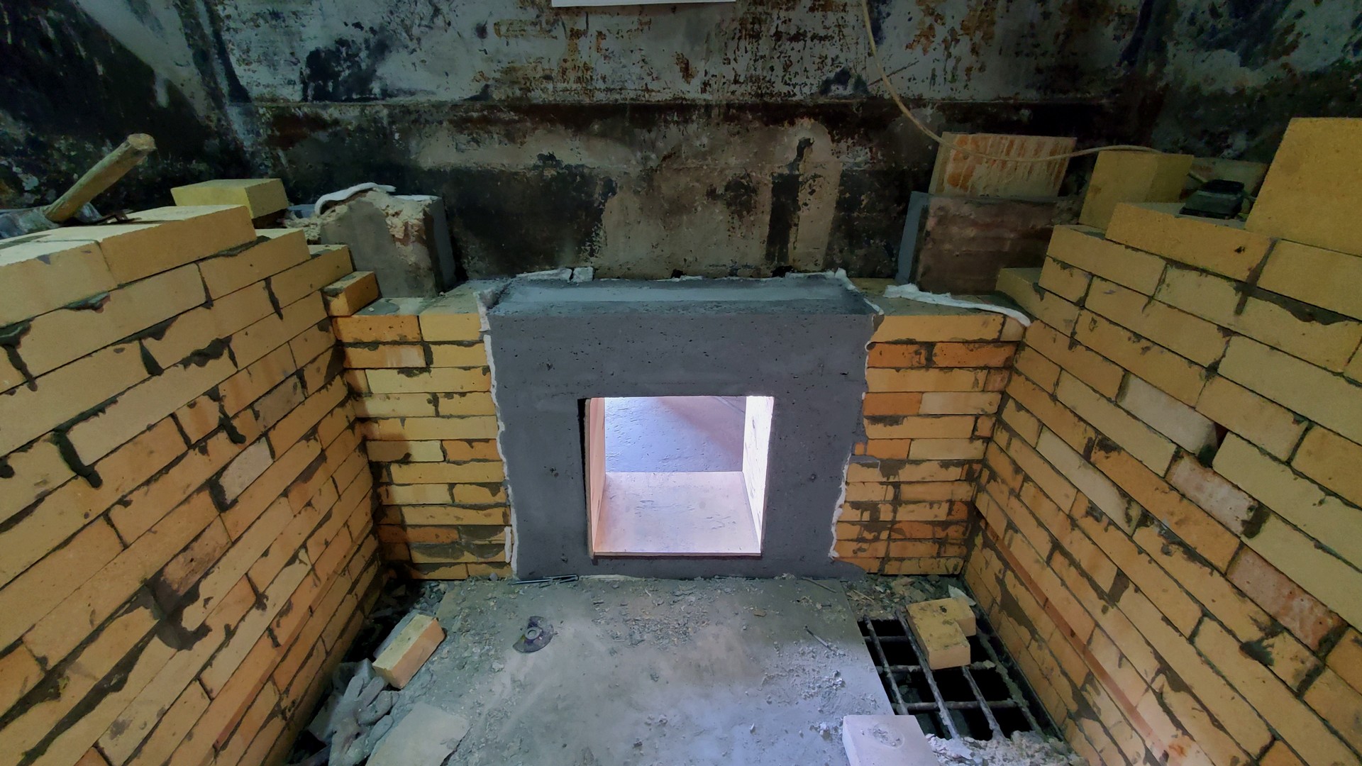
LINING OF FUEL CHUTE, TECHNOLOGICAL HATCHES – single-layer lining, monolithic refractory BORCAST-55W is used as a working layer lining. The stages of work on the installation of concrete lining are described below.
Fuel chute lining:
- Refractory concrete mass is poured into a pre-assembled formwork that provides opening angles, thickness and other structural characteristics.
- Until the final installation of the formwork, anchors are installed, and the entire metal surface of the gutter is pasted over with 10 mm thick Durablanket 128 thermal insulating roll material to compensate for various thermal expansions of steel and refractory lining.
- To reduce the load on the upper part of the chute lining (on the horizontal roof of the chute), additional installation of supports / consoles is performed. These calipers compensate for the pressure from the vertical end masonry of the wall and provide a long service life for the lining of this assembly.
- Refractory concrete mix is prepared in a forced-type paddle mixer, to which the required amount of water (no more than 6-7%) is added to achieve the required consistency of the concrete mass.
- Concrete is placed using a deep vibrator. The use of a vibrator is necessary to achieve the required density and, accordingly, the strength of the concrete.
- After the concrete has set (usually after 8-10 hours), the formwork is carefully dismantled, further work can be continued.
Lining device for the access hatch and hatch door:
All the above stages of work on the installation of a monolithic refractory lining for the fuel chute (installation of anchor products, manufacture of formwork, installation of roll heat-insulating material, installation of an unloading support / console, production of concrete mass and its laying, etc.) correspond to the stages of work on the arrangement of the lining technological hatch and hatch door, respectively.
Please note that the boundary of the monolithic lining and the vertical wall of the refractory lining are glued with 10 mm thick Durablanket 128 thermal insulation roll to form an expansion joint necessary to compensate for various thermal expansions of concrete and brick lining, especially at the initial stage of operation - the stages of drying and heating the boiler lining ...
The formwork of the hatch / cover must take into account the device of the chamfers of the lateral edges of the lining to ensure normal opening / closing of the door during the operation of the boiler.
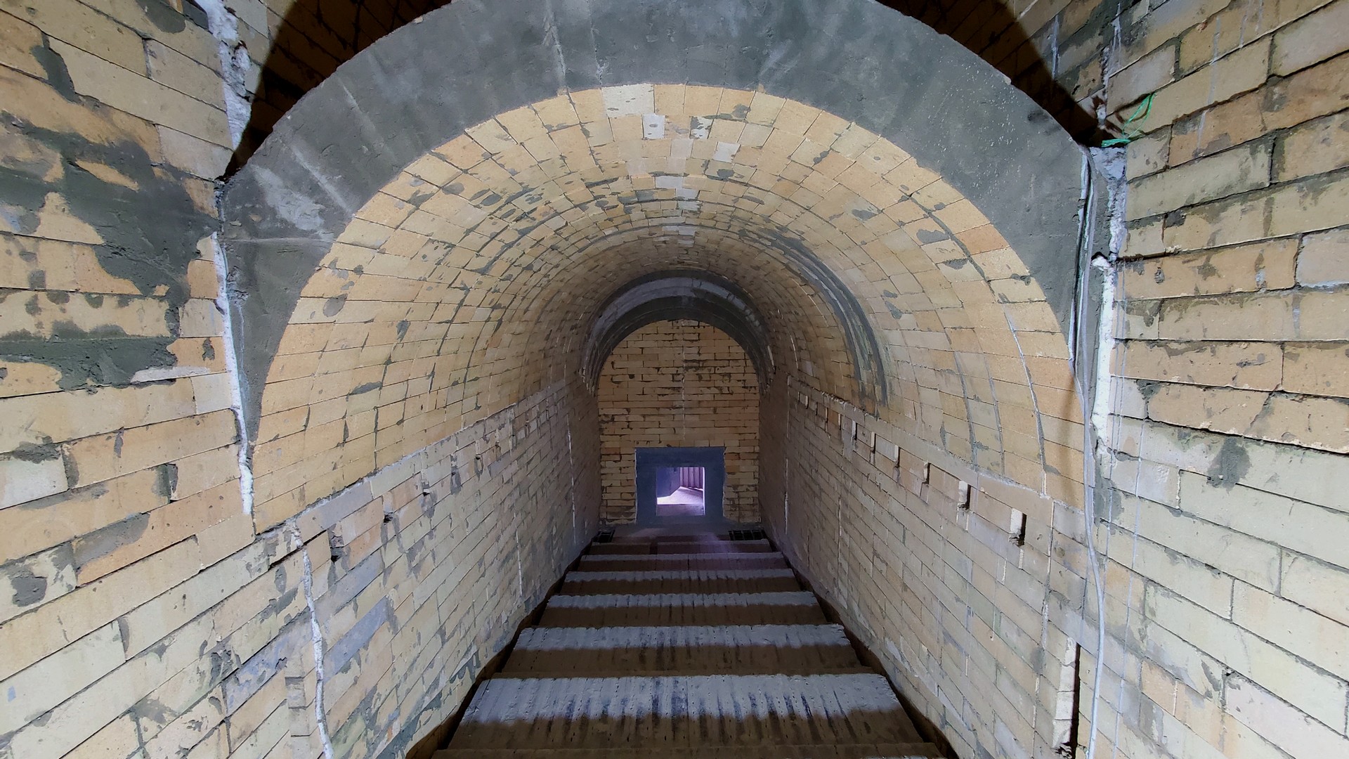
ARCH LINING:


One of the most difficult and critical areas of the boiler furnace lining. Single-layer lining, layer thickness 200 mm. The vault is assembled according to the preliminary layout of shaped bricks. Compacted fireclay bricks of the ShTsU-4.5 brand are used as a refractory. This type of brick has increased strength characteristics, as well as a higher Al2O3 content in relation to ША-I, which is an important factor when choosing a refractory for the boiler roof structure.
The presence of the correct engineering, the required number of fittings, the manufacture of the appropriate formwork for the roof structure, the availability of highly qualified personnel are the necessary conditions for the successful implementation of lining works on the installation of the boiler furnace roof. The stages of work on the installation of the boiler roof are shown below:
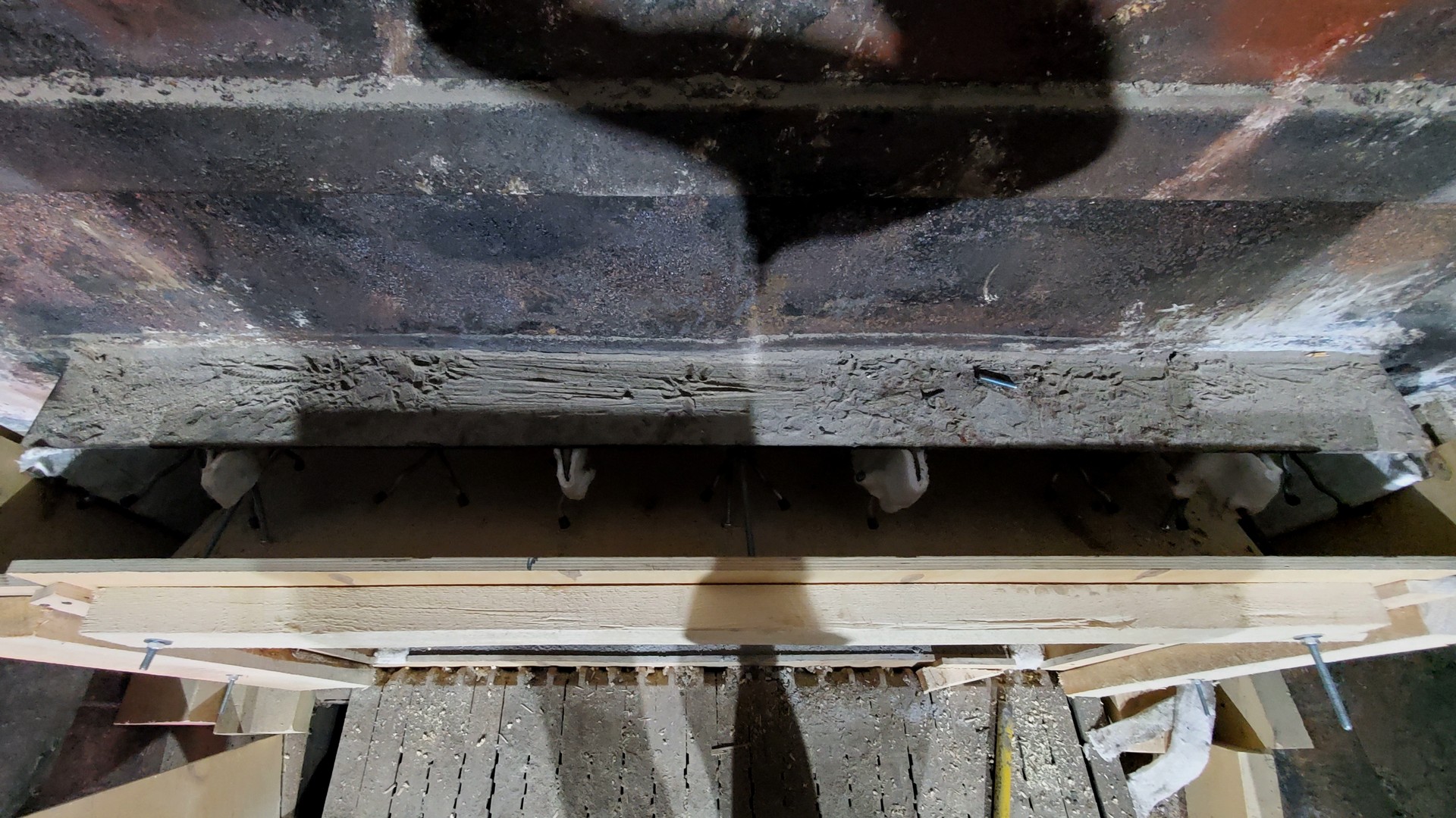
- Formwork / circle production is an important stage of work. It is necessary to make sure in advance that the dimensions and strength of the structure are correct - it must repeatedly withstand the loads when laying the vault, as well as repeated movements during lining work.
- It is necessary to check in advance the correctness of the layout and its compliance with the actual execution. It is necessary to lay the shaped brick arch on the site “on dry” and, if necessary, make the necessary adjustments to the layout.
- To provide additional strength of the arch structure, each segment / arch of the arch rests on individual calipers installed on both sides (the calipers are made of high-alloy heat-resistant steel AISI 310S or from heat-resistant steel 20X23H18). In the ash part of the boiler, in the area of ash discharge, the roof has an inclined structure. The formation of the inclined part is carried out by displacing the subsequent arch of the roof in height by a row of bricks (by 65 mm) in relation to the previous one. In total, the inclined vault is 6 arched rows with a height offset.
- When the inclined section of the vault passes into the horizontal one, one common segment is used as a relief support / console for 6-7 arched rows of the vault.
- The formation of the nozzles was carried out by fitting / sawing out refractory bricks and lining the existing metal tuyere tubes (air supply to ensure normal fuel combustion).
- The base of the vault is wedged with refractory bricks to ensure the required rigidity / strength of the structure (the size is adjusted on site).
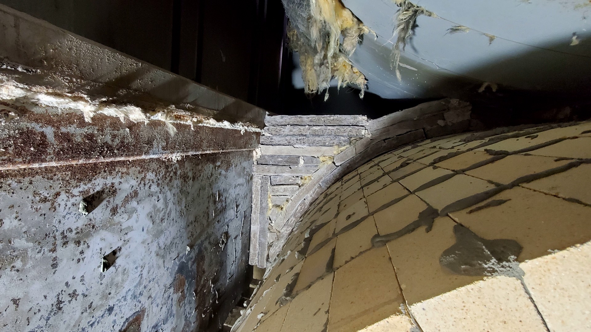
- Formed "pockets" between the arch and the metal body of the furnace, after installing the heat-insulating calcium silicate plate, is poured with refractory concrete to the level of the first row of vertical walls in the section of the second arch.
- Sections of vertical walls in the fuel loading zone rise to the level of the overlap of arch # 2.
- On the end walls of the boiler furnace, thermal expansion joints are additionally formed, which ensure the removal of thermal stresses in the lining during operation of the boiler. The arrangement of these heat seams is similar to the design described in the section LINING OF VERTICAL WALLS.
2. ZONE OF THE SECOND VENTURE.


The design of the lining of the vertical walls, as well as the design of the roof section of the lining, are similar to the design of the lining of the zone of the first roof of the furnace of the boiler described above.
Wall and vault lining:
- To continue laying vertical walls, the heat-insulating layer is raised to the required height along the entire perimeter of the firebox body.
- Installation of anchors in masonry is carried out to ensure the structural strength of the masonry and prevent delamination of the lining. during the operation of the boiler.
- The installation of unloading consoles / supports for the second vault is carried out, after the walls have been lifted in accordance with the project documentation.
- The panels are formed by means of expansion joints.
- Laying of walls with panels in bandaging, arrangement of heat seams, installation of anchor products, formation of tuyere holes, installation of supports / consoles for arched rows of the vault, the device of the arches of the second vault themselves is carried out by analogy with the stages of work described in section No. 1 "ZONE OF THE FIRST VENTURE, BOILER HEATING ZONE ".
- Due to the fact that the structure of the vault is “correct” (the diameter of the vault is equal to the width of the inter-wall space), and the thickness of the vaulted brick is 200 mm (with a thickness of the working layer of the walls of 150 mm), the distance between the vault and the heat-insulating layer is minimal. To continue laying vertical walls, it is necessary to level the horizon to ensure high-quality, reliable laying of the walls (similar to how it was done for the vault No. 1). In order to obtain the most reliable structure, refractory concrete BORCAST-55W, which has high strength characteristics, is used as a leveling layer. This measure also allows you to additionally "load" the vault, preventing its "disclosure" during operation.
- In the zone of the second vault there is an inspection, technological hatch necessary for boiler maintenance - cleaning the boiler from ash deposits in the inter-roof space and monitoring the technical condition of the boiler lining, as well as for access to the fire-tube drum. For the lining of this unit, BORCAST-55W monolithic refractory concrete is used.
- The technology of laying refractory concrete, preparation of the installation site, installation of anchor products, installation of heat seams by pasting 10 mm thick Durablanket 128 thermal insulation roll material, installation of an unloading slide, manufacturing and formwork - all this, as well as other necessary work, are described in the section # 1 above.
3. ZONE OF THE THIRD COVERAGE.


The design of the lining of the vertical walls, as well as the design of the roof section of the lining, are similar to the design of the lining of the zones of the first and second vaults of the boiler furnace, described above.
Wall and vault lining:
- The installation of the heat-insulating layer, as well as the laying of concrete as a leveling layer for the continuation of the laying of the vertical walls of the zone of the third boiler vault, including the laying of walls with panels in the ligation and the installation of masonry anchors and supports for the vault, is carried out in the same way as the stages of work described in previous sections.
- The space formed between the third roof and the fire-tube drum of the boiler is filled with kaolin plates, which primarily function as a heat-insulating layer, and secondly, the roof is additionally loaded, preventing its "opening" during the operation of the boiler lining (plate density up to 350 kg / m3) ...
Outlet shaft / firebox neck:
- • The transitional section of masonry of vertical walls with the convective part of the boiler / collectors of water screens, as well as the roof part (third vault) with a fire tube drum are framed by a concrete belt made of monolithic refractory.
- • Before the installation of the formwork, the supporting structures of the boiler (boiler beams) are cleaned from the remnants of old concrete, anchors are welded on, an expansion joint is formed along the concrete / brick boundary, and the formwork is installed around the entire perimeter of the shaft / mouth of the furnace.
- • The concrete is poured in one step; after the monolithic refractory has set, the formwork is carefully dismantled.
SUMMARY OF THE PROJECT:
The main difficulty of the boiler lining project No. 1 at the FM-Sever LLC job site is the need to install three vaults in the boiler furnace, which form the movement of combustion products according to the manufacturer's boiler design. Using the previous experience in the implementation of the project for replacing the lining of a hot water boiler No. 2, highly qualified lining specialists and the assistance of FM-Estate LLC specialists in solving any organizational issues - all this made it possible to implement this project in 13 days (!), including work on tearing down the existing refractory!