On November 4, 2019, LLC “Wellons.ru” successfully completed a project to replace the refractory lining of the boiler No. 2 (KTV-5000) with the boiler house of FM Estate LLC. These works were carried out on the terms of an EPC contract, including engineering, selection and delivery of materials, as well as lining of the refractory lining of the boiler.
ENGINEERING.
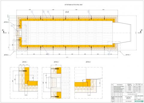
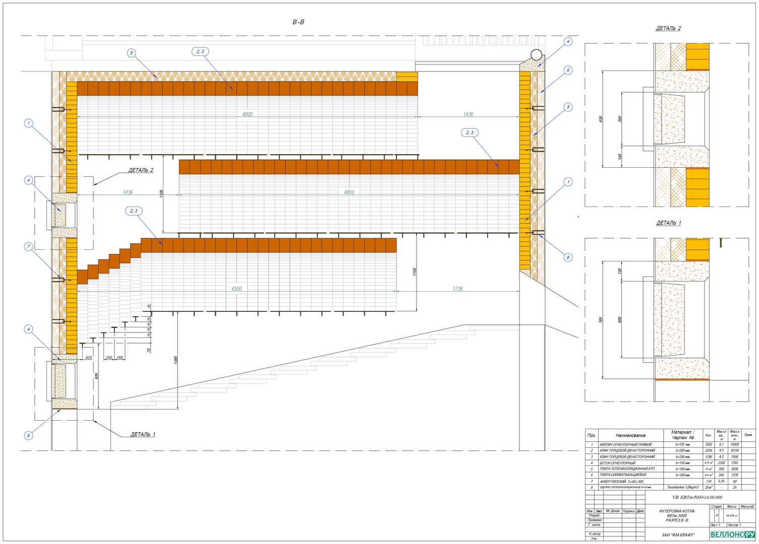
On the basis of the received sketch of the boiler plant, the specialists of Wellons.RU LLC developed a detailed design of a refractory lining device using a multilayer structure (two-layer heat-insulating lining and a working layer lining using refractory bricks).
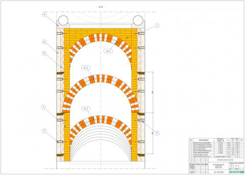
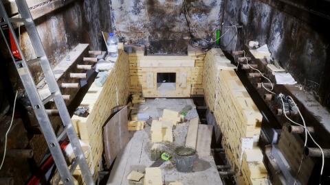
The main complexity of this project is the arrangement of three vault structures in the boiler furnace to ensure the design features of the boiler installation of the KTVV-5000 boiler manufacturer (Kovrovsky Boiler Plant LLC, Kovrov city). To ensure the strength of the construction of the masonry of the vaulted part, as well as the brickwork of the straight walls, a number of technical measures were carried out using special supports and anchor products for brickwork.
SELECTION AND DELIVERY OF THE REFRACTORY.
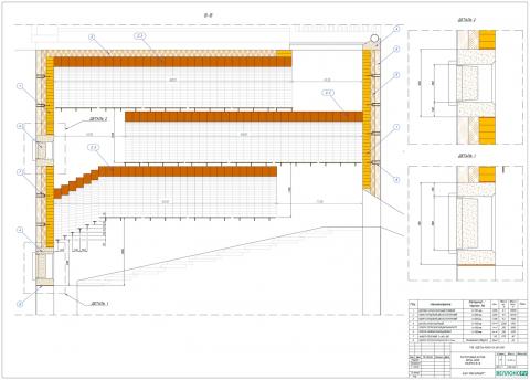
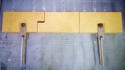
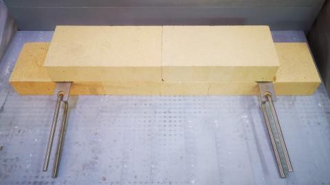
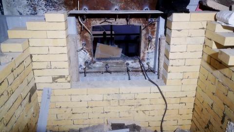
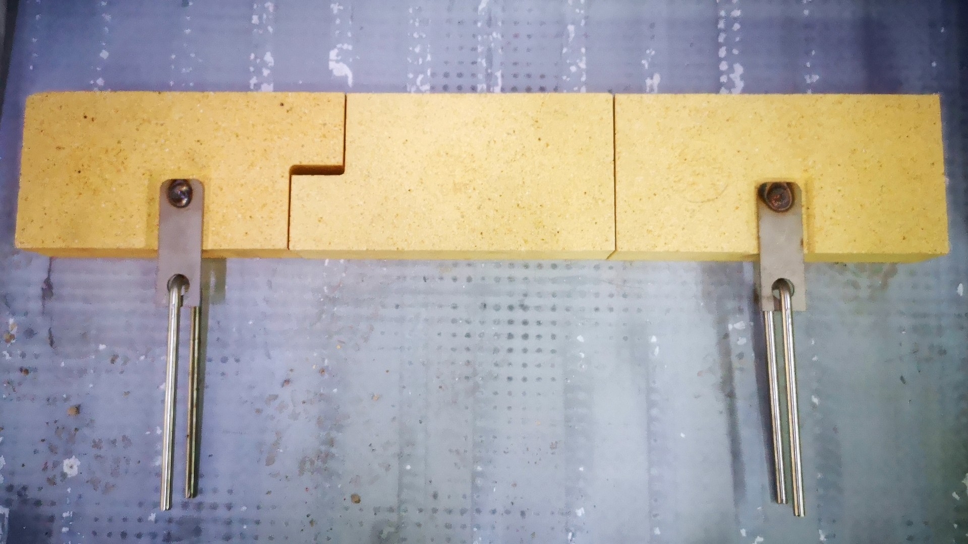
Plot of vertical straight walls of the boiler. To ensure normal lining service of the vertical straight walls of the boiler, a device of “separate” panels with a compensating heat seam is provided. This seam is formed through the use of refractory bricks made according to individually developed drawings. The panels are laid in the dressing using a special brick under the anchor. All “drawing” products (products not in accordance with GOST), as well as all anchor products are made according to the drawings of Wellons.RU LLC, specially designed for this project. Installation of anchors, for masonry, is carried out every 6-9 rows (determined locally, depending on the horizontal level of the inclined grate).
ShA-I brand refractory brick (layer thickness 150 mm.) With a working temperature of up to 1350-1400 ° C was used as a working layer refractory, KTP-50 kaolin plate (100 mm in two layers) as the first heat-insulating layer. with operating temperature up to 1250 ° С,
as a second heat-insulating layer - calcium silicate plate type SILBORD (one layer with a thickness of 100 mm.) with a working temperature of application up to 1100 ° C. The total thickness of the lining is 350 mm. For the formation of temperature joints, a roll insulation material (blanket) Durablanket 128 with a thickness of 10 mm with an operating temperature of up to 1250 ° C is used.
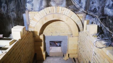
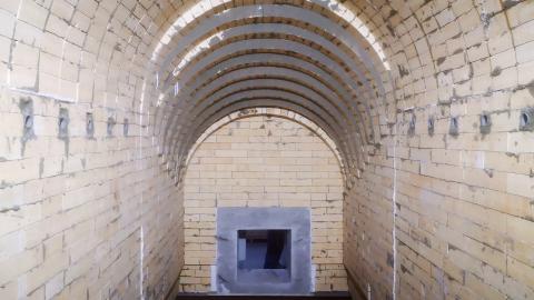
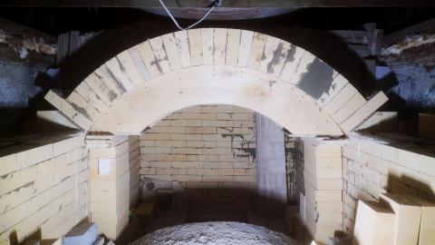
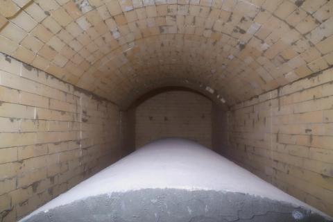
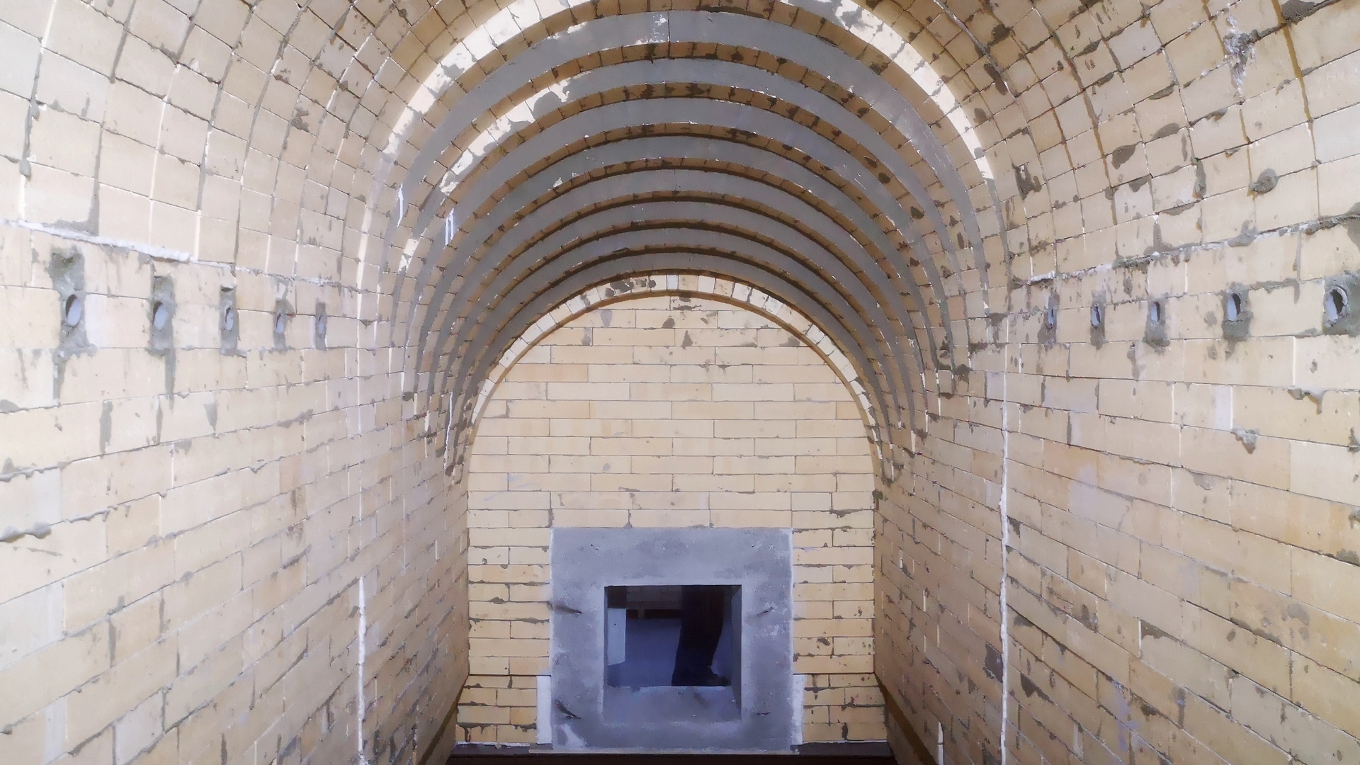
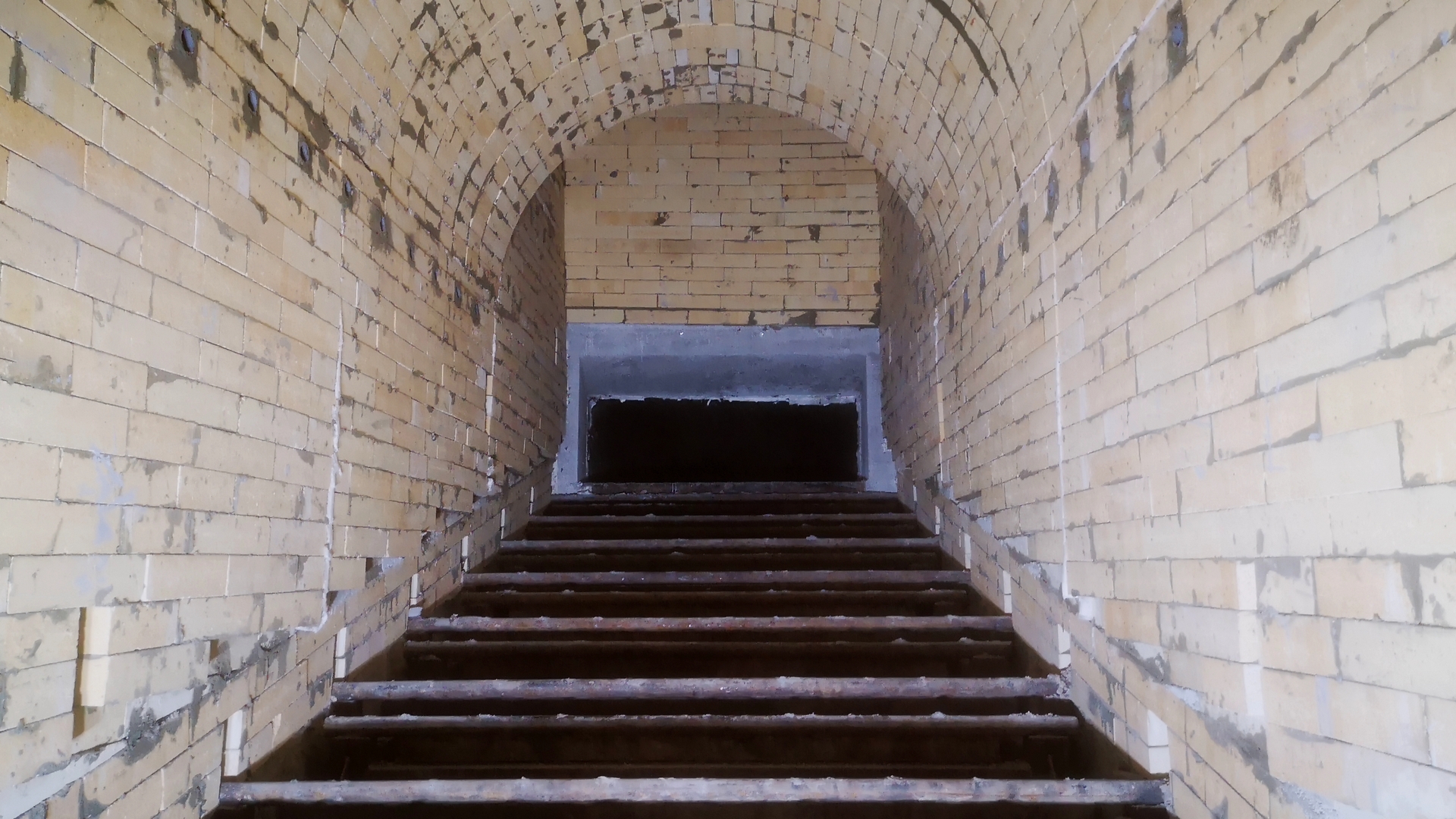
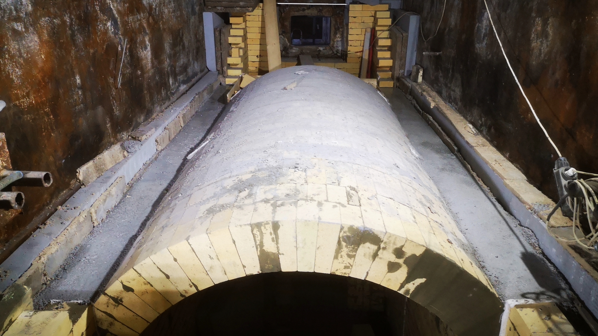
The boiler arch (three arches). To ensure the maximum possible structural strength of the boiler’s roof, the design of the roof was changed from a flatter roof to a steeper roof - the “right” roof, the diameter of which is actually equal to the width of the wall between the walls of the boiler. At the same time, the cross sections both in the lower part of the boiler (fuel combustion zone) and in the zones of combustion products movement did not decrease. Thus, a change in the design of the arches does not affect the technological process of burning fuel, as well as heating the coolant in the boiler.
ShTsU-4,5 brand shaped brick was used as a refractory for the arch device according to a previously developed layout of the refractory. The thickness of the arch is 200 mm. This brick thickness, as well as the use of shaped products, allows you to ensure maximum strength of the arch structure.
Additionally, in order to give strength to the vaulted design of the boiler furnace, consoles / calipers were used that reduce the pressure of the roof lining on the vertical walls of the boiler, providing the necessary rigidity and strength of the lining structure as a whole.
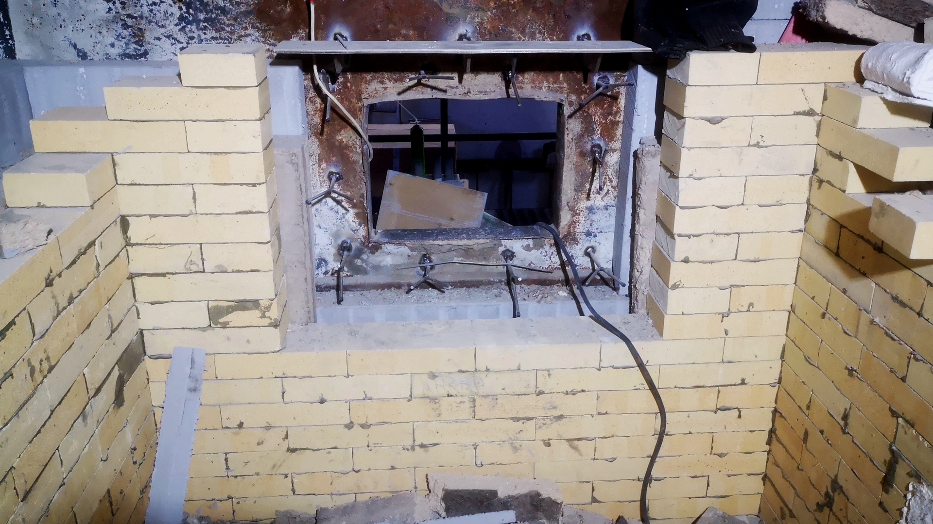
Technological hatch and doors. The lining of these units is carried out using a monolithic refractory - BORCAST-55W refractory concrete with an Al2O3>55% with an operating temperature of up to 1450 ° C. Concrete is laid in a pre-installed formwork using a deep vibrator to compact the concrete mass. Metal anchors made of high-alloy heat-resistant steel AISI 310S (20X23H18) are used.
INSTALLATION WORKS.
All work related to the construction of a refractory lining, such as: installation of a refractory, necessary auxiliary work (formwork, tooling and other works) was carried out by the specialists of LLC Wellons.RU together with a team of lining workers under a single EPC contract. All main types of work are described below in the relevant sections. They will also be presented in our short video reports on the company’s website in the section “CAPITAL REPAIR OF THE KTVM-5000 HWH Refractory REPAIR”.
1. FIRST ARCH AREA, GRATES of the BOILER FURNACE AREA.
LAYER DESIGN OF VERTICAL WALLS – two layers of thermal insulation from a kaolin plate with a total thickness of 100 mm and a calcium silicate plate with a thickness of 100 mm .; working layer - made of refractory brick ША-I No. 9, 150 mm thick. and special drawing products for anchor fastening on the basis of ША-I №9. The total thickness of the lining is 350 mm.
Wall lining device:


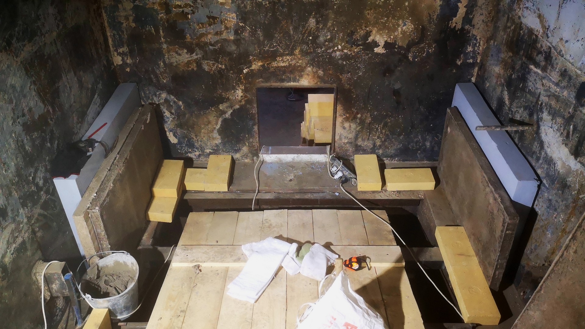
- The heat-insulating layer is arranged using one silicate-calcium plate (100 mm thick) and two kaolin plates (2x50 mm). The plates are mounted on the rib and pressed tightly against each other. The laying of the working layer of bricks provides a strong and reliable fastening of these plates. The structural strength of the plates (they do not crumble during operation) does not require additional fastening to their own anchors or to glue.
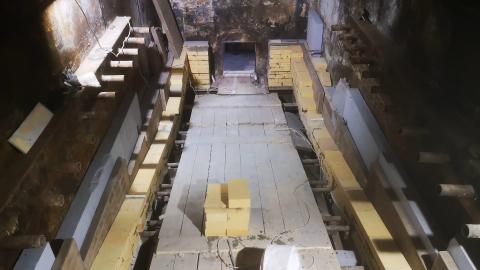
- Important! Due to the fact that the grates design is inclined, the main task of arranging the bottom of the lining of the walls of the boiler furnace is to level the brickwork of the working layer horizontally. This is a necessary measure to ensure compliance with the requirements for laying refractory bricks and ensure the normal life of the lining of the entire boiler.
- When laying the bottom row of refractory bricks, we saw deviations in the size of the inner grate from the design dimensions. Those. the width of the grate zone is ~ 100 mm narrower than indicated on the boiler sketch (the width of the “false” shell of the boiler for supplying combustion air is not shown). Thus, in order to ensure the movement of the movable beams of the grate, for the possibility of installing protective "cheeks" of the grate, we were forced to reduce the thickness of the heat-insulating layer by 50 mm on each side to a height of ~ 250 mm (four rows of bricks). After that, the thickness of the lining, due to the displacement of the brick of the working layer inside the grate zone by 50 mm, began to correspond to the design. These changes, on the technological process or on the structural strength of the lining, do not have a negative effect.
- The refractory layer of the working layer, the brickwork of the first row, is laid on a Durablanket 128 coil insulation material 10 mm thick to compensate for various thermal expansions of steel and refractory lining.
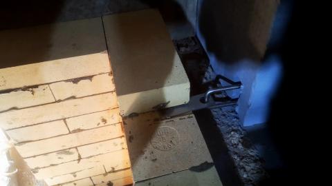
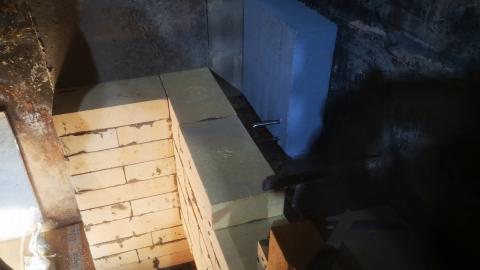
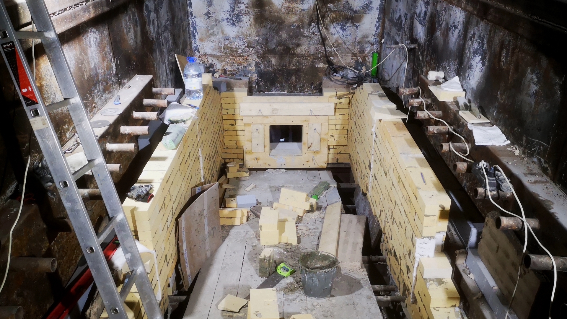
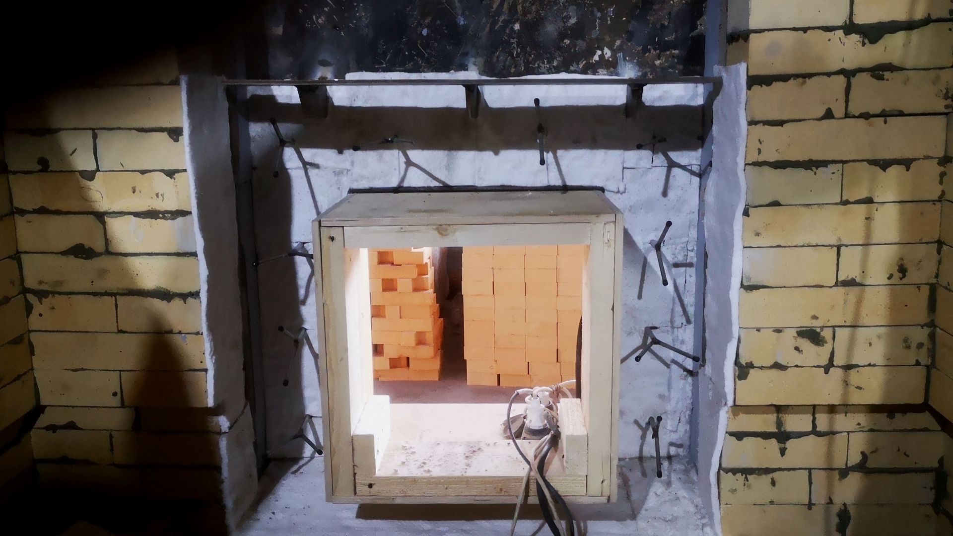
- Brickwork of vertical walls is carried out by panels with a width of ~ 1500 mm with the formation of a temperature joint. To ensure structural strength, the laying of these panels is carried out using specially designed products / bricks with a recess and a hole for the anchor, as well as special bricks "with a tooth" to form a direct Z-shaped seam. The purpose of this Z-shaped seam is to prevent direct exposure to high temperature on the heat-insulating layer, the operating temperature of which is significantly lower layer; additional strength - preventing the masonry from falling out at the joints of panels.
- As a temperature seam of the panel joints, a 10 mm thick Durablanket 128 thermal insulation material is used.
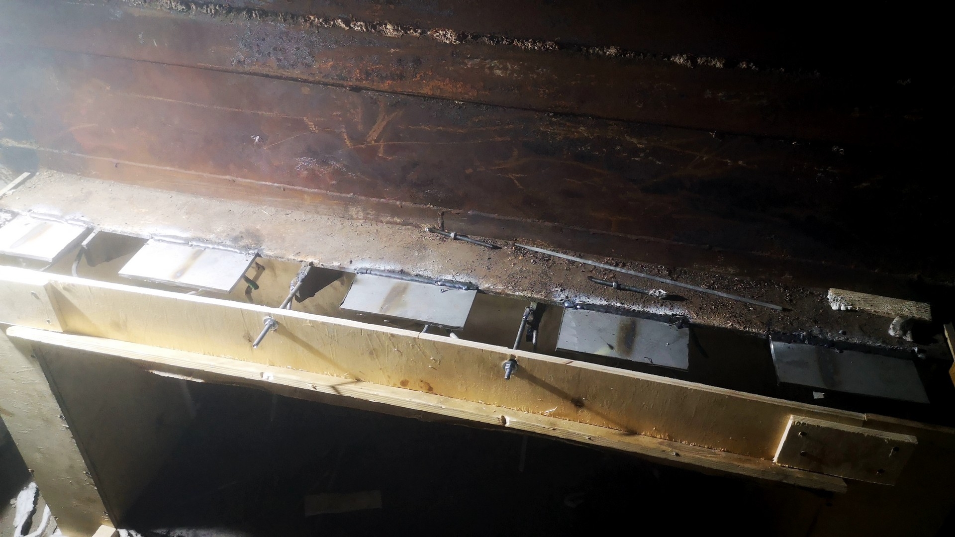
- To ensure the structural strength of the refractory lining, metal anchors are used from high-alloy heat-resistant steel AISI 310S (or from heat-resistant steel 20X23H18). Anchors are installed according to their layout on the 6th – 9th row of masonry (depending on the angle of inclination of the grate). The anchor eye is welded to the boiler body, and the possibility of moving a flat anchor vertically along the entire height of the eye makes it easy to install this anchor in the groove of the refractory brick, providing the ability to compensate for the thermal expansion of the lining, while maintaining structural strength.
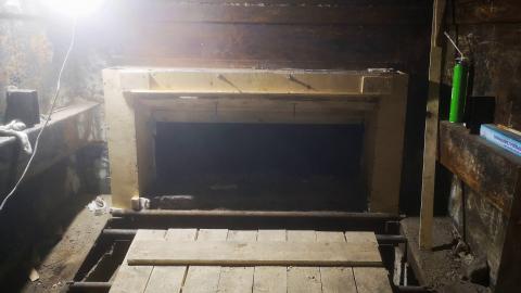
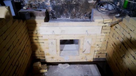
LAYER DESIGN OF THE FUEL TUBE, TECHNOLOGICAL HATCH AND HATCH DOOR – the lining is single-layer, the BORCAST-55W monolithic refractory is used as the lining of the working layer. The thickness of the lining depends on the design features of a particular site and varies from 210 to 350 mm. The stages of the construction of concrete refractory lining are described below.
Fuel trough lining device:
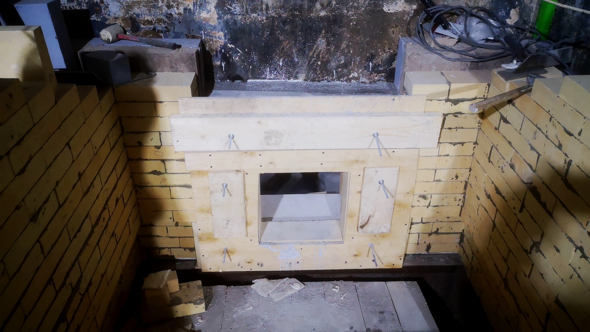
- Refractory concrete mass is poured into pre-mounted formwork, which provides opening angles, thickness and other characteristics.
- The formwork is made of plywood 12 mm thick, the details of which are lubricated with machine oil to ensure normal peeling of the plywood sheets when dismantling the formwork, respectively, after setting and the necessary strength of the refractory concrete after pouring.
- Until the final installation of the formwork, anchors are installed, as well as the entire metal surface of the gutter is glued with 10 mm thick Durablanket 128 insulation roll material to compensate for various thermal expansions of steel and refractory lining.
- To reduce the load on the upper part of the lining of the gutter (on the horizontal arch of the gutter), additional installation of calipers (supports) / consoles is performed. The caliper data fully compensates for the pressure from the vertical end masonry of the boiler furnace wall and ensures a long lining life of this unit.
- The refractory concrete mixture is prepared in a concrete mixer (for heavy concrete it is preferable to have a forced-type paddle mixer) into which the required amount of water (not more than 6-7%) is added to achieve the required consistency of the concrete mass.
- Concrete is laid using a deep vibrator. The use of a vibrator is necessary to achieve the required density and, accordingly, the strength of concrete.
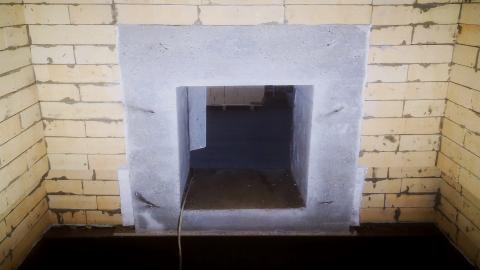
- After the concrete has set (usually after 8-10 hours), the formwork can be carefully dismantled, further work on the lining device is continued.
Lining device for the technological hatch and the hatch door:
- All of the above stages of the installation of a monolithic refractory lining for a fuel trench (installation of anchor products, formwork, installation of heat-insulating roll material, installation of an unloading support / console, production of concrete mass and its laying, etc.) correspond to the stages of the installation of a lining technological hatch and hatch doors, respectively.
- Please note that the border of the monolithic lining and the vertical wall of the refractory lining is glued with 10 mm thick Durablanket 128 heat-insulating roll material to form the temperature joint necessary to compensate for various thermal expansions of concrete and brick lining, especially at the initial stage of operation - the stages of drying and heating of the boiler lining.
- The formwork of the hatch / lid itself must take into account the device of the chamfers of the lateral faces of the lining, to ensure the normal opening / closing of the door during operation of the boiler and access inside for maintenance, and inspection of the internal state of the furnace.
- After the completion of concrete work (usually after 8-10 hours), the formwork can be carefully dismantled, further work continues.
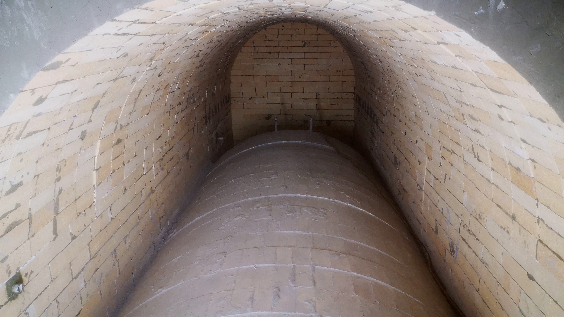
ARCH LINE DESIGN:
One of the most difficult and critical areas of the lining of the boiler furnace. Lining is single-layer, layer thickness 200 mm. The arch is put together according to the preliminary layout of shaped bricks. As a refractory, compacted fireclay brick of the ShTsU-4,5 brand is used. This type of brick has increased strength characteristics, as well as a higher Al2O3 content with respect to ША-I, which is an important factor when choosing a refractory for the boiler arch design.
The presence of detailed engineering, the required number of fittings, highly qualified personnel are the necessary conditions for the successful implementation of lining work on the installation of the boiler furnace arch. The steps for installing the boiler roof are shown below:
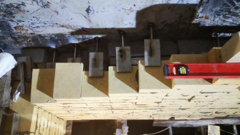
- To ensure additional strength of the arch, each segment / arch of the arch rests on individual calipers installed on both sides (calipers are made of high-alloy heat-resistant steel AISI 310S / 20X23H18). In the ash part of the boiler, the arch has an inclined design. The inclined part is formed due to the displacement of the subsequent arch of the arch in height by a row of bricks (by 65 mm) relative to the previous one. Total, the inclined vault - 10 arched rows with a displacement in height.
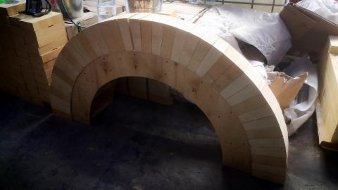
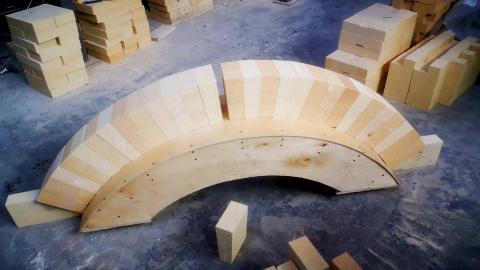
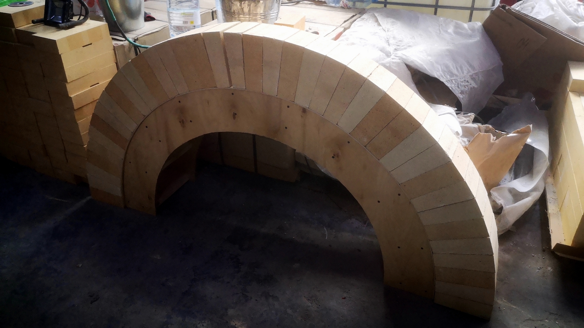
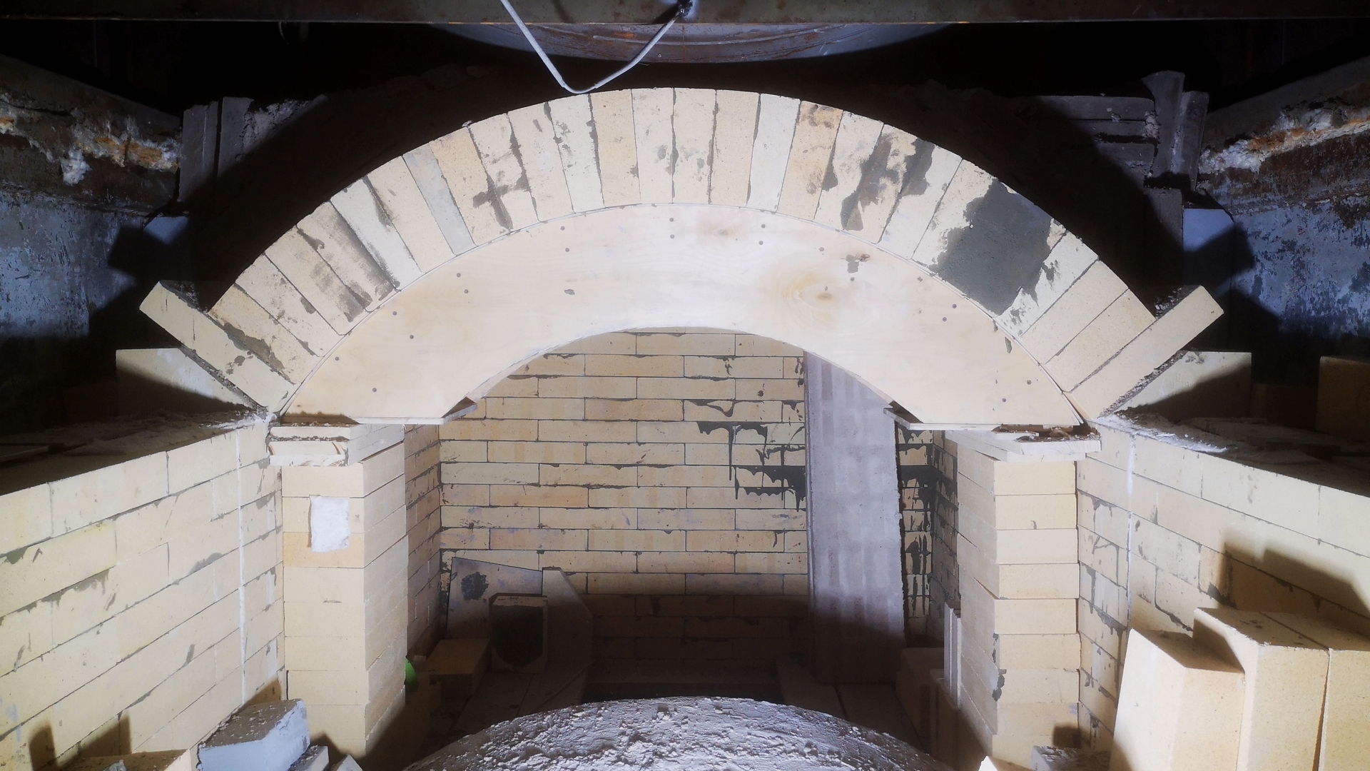
- The manufacture of formwork / circles is an important stage of work. It is necessary to make sure in advance that the dimensions and strength of the structure are correct - it must withstand loads when laying the arch, as well as multiple movements during lining operations.
- It is necessary to check in advance the correctness of the layout and its conformity to the actual performance, put the arch of shaped bricks on the site “dry” and, if necessary, make the necessary adjustments to the layout.
- The laying of vaulted brick, as well as the main laying of the furnace walls, is carried out using the FOSCON chemical solution used as mixing water for the preparation of masonry mortar based on the mortar MS-28. The use of this solution allows to provide a hardening solution in a short time without exposure to high temperatures, which greatly speeds up the process of lining operations in general.
- When the inclined section of the arch becomes horizontal, one common segment is used as an unloading support / console for 6-7 arched rows of the arch.
- In order not to violate the design of the arch, the first row of the masonry of the arch is shifted up 4 rows, due to the presence of combustion air ducts. Lance (tuyere) holes were left in the vertical part of the walls of the vault. To form nozzle openings, plastic tubes and a plastic consistency of masonry mortar based on mortar and chemical solution of mixing water were used. The space between the plastic tubes and the brick was filled with plastic mass, which after hardening and burning of the pipes forms a tuyere hole for supplying air to the combustion zone.
- The sections of the vertical walls in the fuel loading zone were raised to the level of overlap of the arch of arch No. 2
2. SECOND ARCH AREA.
The design of the lining of the vertical walls, as well as the design of the arch portion of the lining, are similar to the lining of the zone of the first arch of the furnace part of the boiler described above.
Wall and arch lining device:
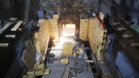
- To continue laying vertical walls, the insulating layer rises to the required height around the entire perimeter of the furnace body.
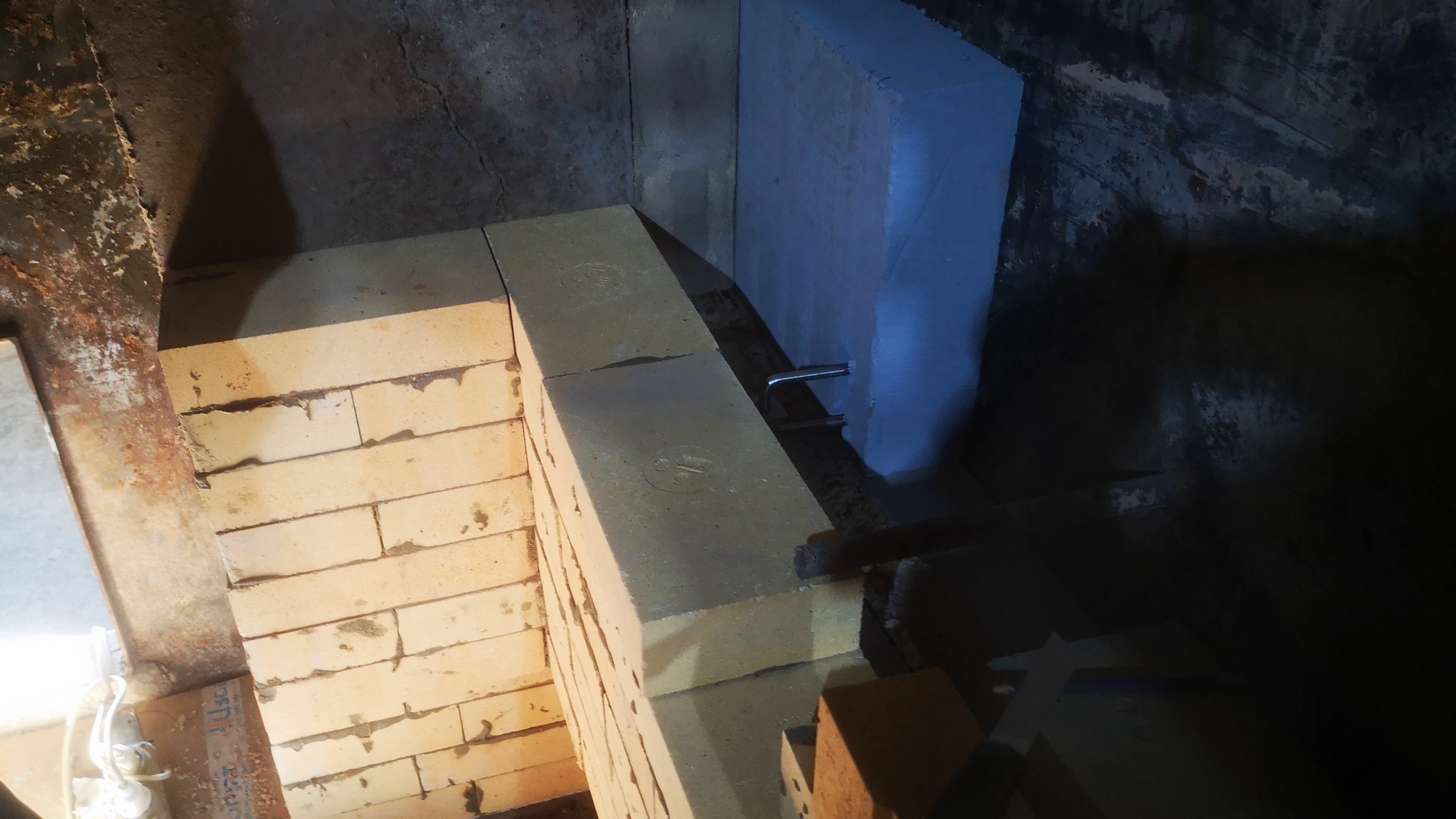
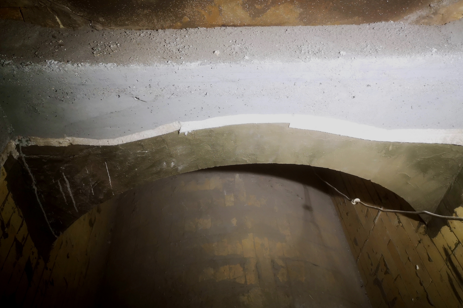
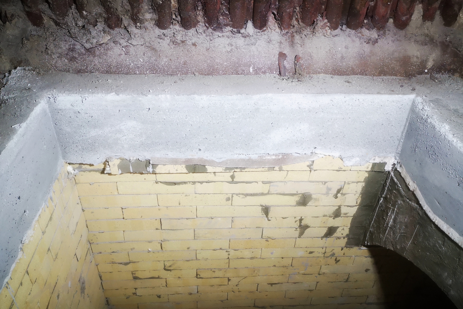
- Due to the fact that the design of the arch is “correct” (the diameter of the arch is equal to the width of the inter-wall space), and the thickness of the vaulted brick is 200 mm (with the thickness of the working layer of the walls being 150 mm), the distance between the arch and the insulating layer is minimal. And, accordingly, to continue laying vertical walls, it is necessary to level the horizon to ensure high-quality, reliable laying of walls. In order to obtain the most reliable design, BORCAST-55W refractory concrete with high strength characteristics is used as a leveling layer. Concrete rises to form a leveled surface with a width of at least 150 mm, which is necessary to ensure a normal fit of the brick surface of the working layer of the furnace walls to the base of the leveled concrete.
- This event also allows you to additionally "download" the arch, preventing its "disclosure" during operation.
- Laying the walls with panels bonded brickwork, arranging heat seams, installing anchor products, forming tuyere holes, mounting calipers / consoles for arched rows of arches, installing arches of the second arches themselves is carried out by analogy with the steps described in section No. 1 “FIRST AREA ZONE, GAS BURNER HEATING AREA”.
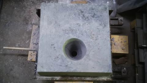
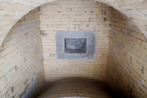
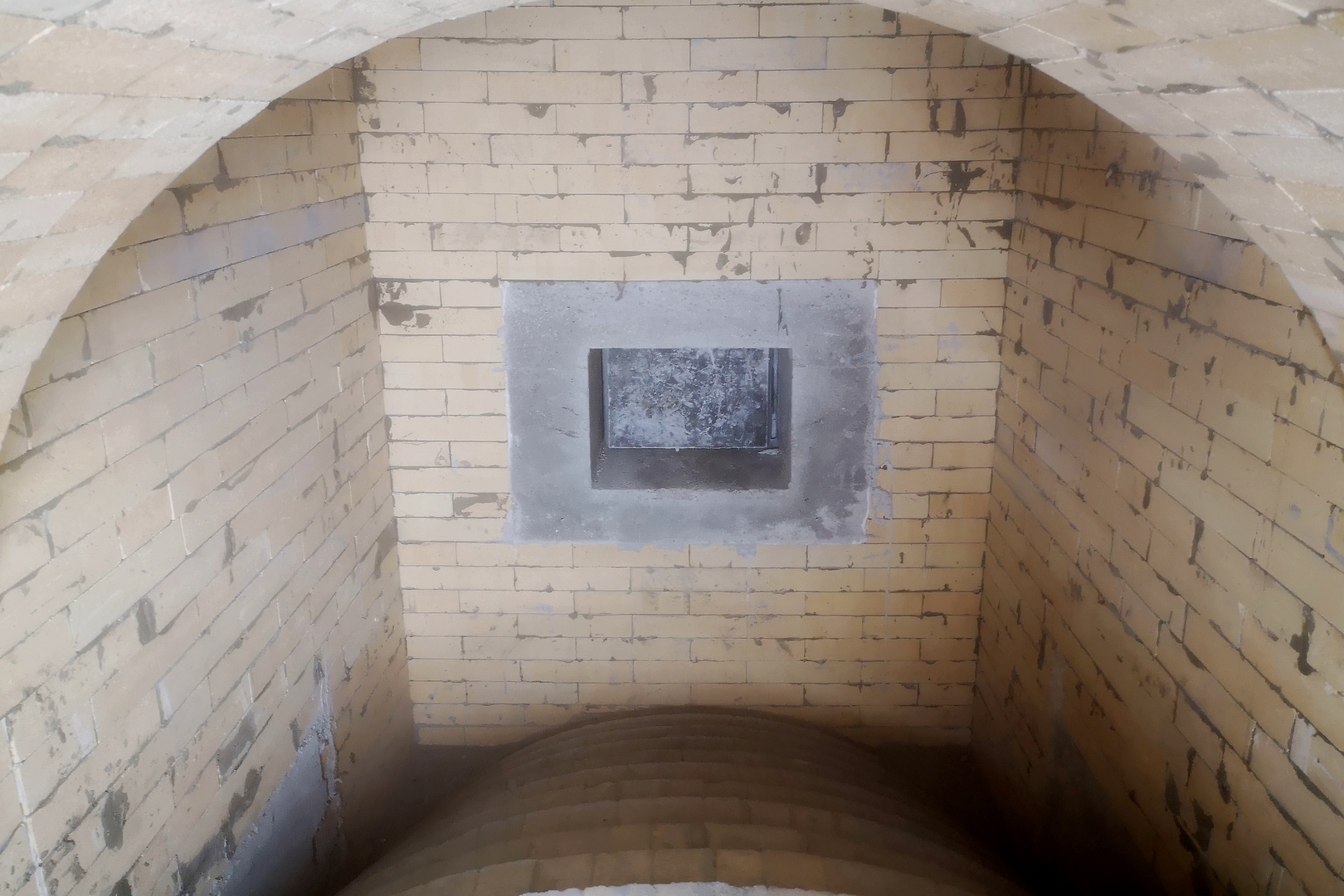
- In the area of the second roof there is a viewing, technological hatch necessary for servicing the boiler - cleaning the boiler from ash deposits in the inter-arch space and monitoring the technical condition of the boiler lining, as well as for access to the fire tube. Lining design: single-layer, monolithic. For lining this unit, BORCAST-55W monolithic refractory concrete is used.
- The technology of laying refractory concrete, preparing the installation site, installing anchor products, arranging heat seams by gluing 10 mm thick Durablanket 128 heat-insulating roll material, installing an unloading support, manufacturing and formwork device - all this, as well as other necessary work, are described in section No. 1 above.
- After the concrete has set (usually after 8-10 hours), the formwork can be carefully dismantled, further work on the lining device is continued.
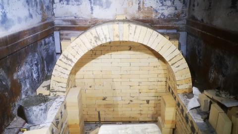
3. ZONE OF THE THIRD ARCH.
The design of the lining of vertical walls, as well as the design of the arch portion of the lining, are similar to the device for lining the zones of the first and second arches of the furnace part of the boiler described above.
Wall and arch lining:
- The installation of the heat-insulating layer, as well as the laying of concrete as a leveling layer to continue laying the vertical walls of the zone of the third vault of the boiler, including laying the walls with panels in the dressing and installing masonry anchors and supports for the vault, is performed similarly to the steps described in the previous sections.
- Due to deviations in the height of the masonry of the vertical sections of the walls in the first two arch zones associated with the structural arrangement of the tuyere holes, as well as to ensure the dimensions of the inter-arch space in the boiler furnace, the construction of the third arch was forced to be revised. It was also necessary to do this due to the lack of sufficient space between the arch and the fire tube.
- A new vault design has been developed, the design of which is as close as possible to the conditions of the “correct” vault. A new formwork was made and on it, at the production site, a vault was laid out “on dry” to verify the correctness of the developed solutions.
- This arch design provides for the installation of heel bricks, which are sawn from a direct, ordinary format and relies on previously welded calipers / consoles. This event allows you to ensure maximum structural strength despite the fact that the arch turns out to be more “flat” with respect to the previously installed / laid arches (the first and second arch sections of the boiler).
- The use of the FOSCON chemical solution used as mixing water for the preparation of masonry mortar based on the МШ-28 mortar allows us to provide hardening of the mortar and structural strength in a short time without exposure to high temperatures - this is especially important when laying arch or other arch structures.
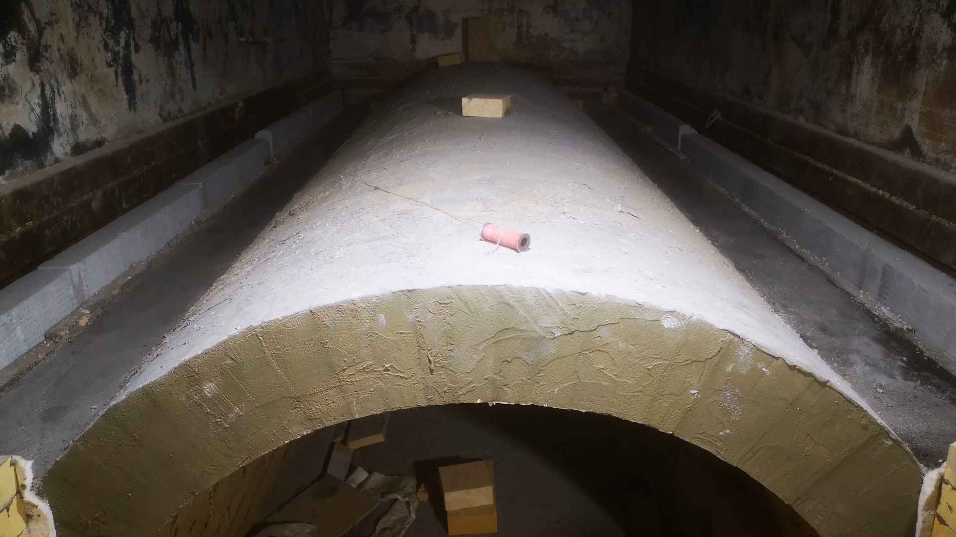
- The space between the third roof and the boiler’s fire tube is filled with kaolin plates, which primarily serve as a heat-insulating layer, and secondly additionally load the roof, preventing it from “opening” during operation of the boiler lining (plate density up to 350 kg / m3).
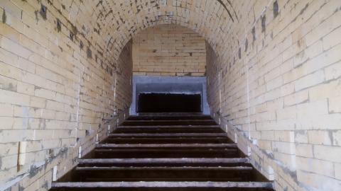
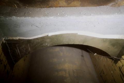
Output shaft / neck of the furnace:
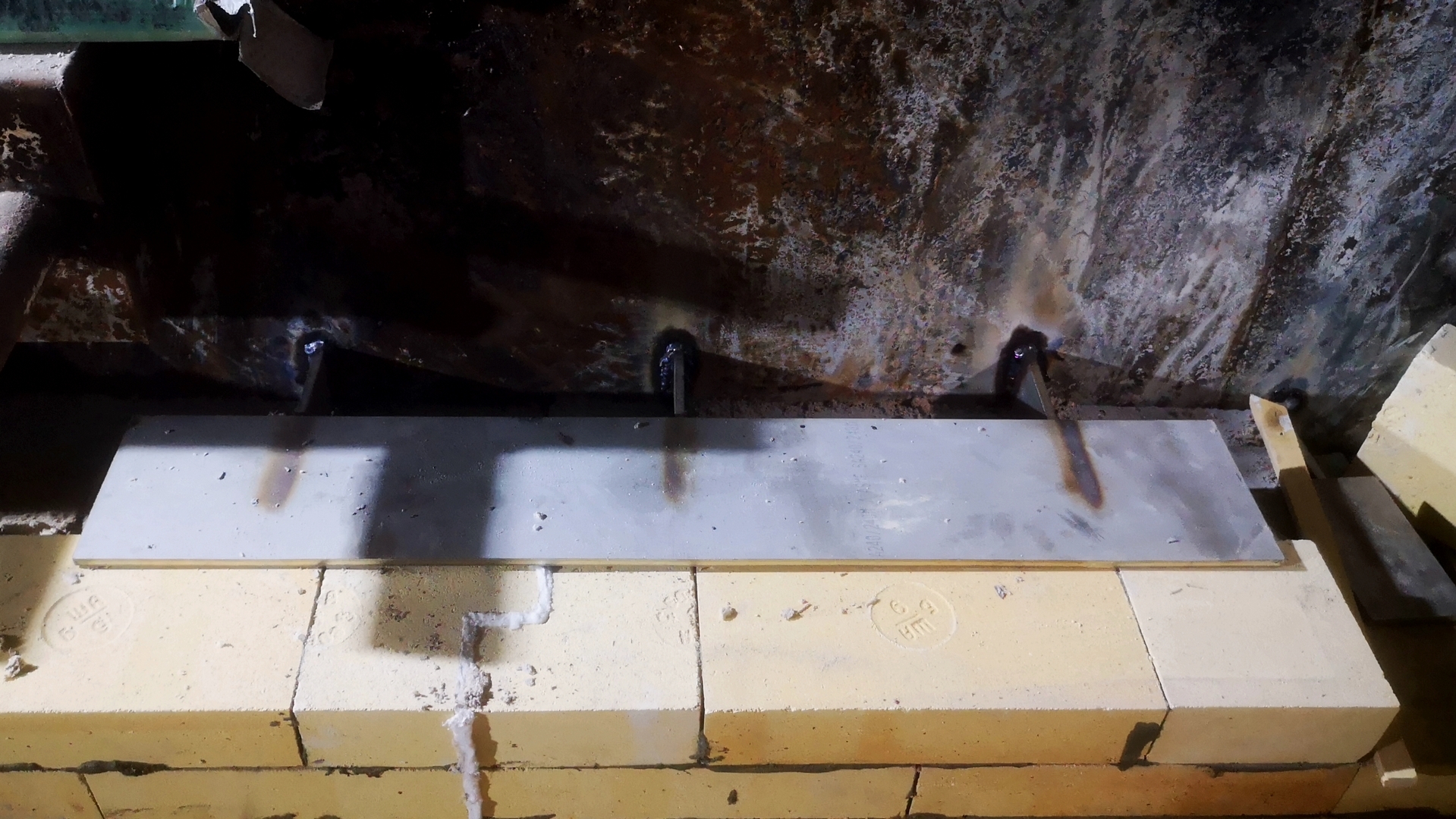
- The transitional section of the masonry of vertical walls with the convective part of the boiler / collectors of water screens, as well as the vault part (third vault) with the fire tube are framed with a concrete belt of cast refractory.
- Before the formwork device, the boiler supporting structures (boiler beams) are cleaned of old concrete residues, anchors are welded, a temperature seam is formed at the concrete / brick border (laid on 10 mm thick Durablanket 128 roll insulation material), the formwork is installed around the entire perimeter of the shaft / neck of the furnace.
- Concrete pouring takes place in one step, after setting the monolithic refractory, the formwork is carefully dismantled.
SUMMARY OF THE PROJECT:
This project of lining the KTVM-5000 boiler is a complex project. The main difficulty of the project is the need for three arches in the boiler furnace, which form the movement of combustion products according to the design of the boiler of the manufacturer. A huge amount of engineering: the development of special anchor products, the manufacture of drawing refractory products, the use of combined solutions (molded and monolithic refractories), as well as the availability of highly qualified liners and the help of FM Estate LLC specialists in solving any organizational issues - all this allowed us to implement this project in 12 days!