1. GENERAL
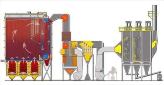
This section provides a description of the equipment, which is included in the scope of "Wellons" supply of one waste incinerator unit (WIU)/boiler with output of 120 MTH of steam. The equipment includes:
- Wood-fired boiler;
- Chamber furnaces;
- Auxiliary equipment;
The system is designed to burn conventional wood fuel with the total moisture content of 55% (on a wet basis). All boiler house systems and vessels designed and delivered under this project are intended for a boiler generating superheated high-pressure steam to be supplied to a steam turbine generator for power generation, or to other process equipment.
The descriptions provided below are based on the proven design of our modern systems operating worldwide. Wellons reserves the right to make any changes in the design of boilers as may be required in view of specific conditions of a particular site, the use of certain components, as well as the application of Wellons' new technical/process solutions.
As an option, Wellons may supply, upon request, the electrostatic precipitator for exhaust gas cleaning and a fuel hopper with a system of conveyors for feeding fuel to furnaces. The design of electrostatic precipitator allows to reduce dust emissions below 50 mg/Nm3.
2. BOILER
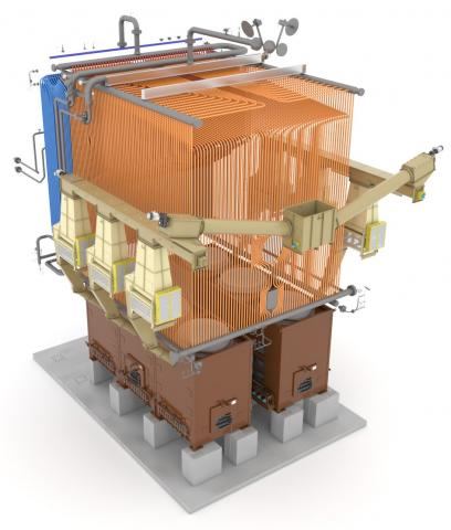
The delivery of one Wellons water-tube boiler is provided for installation directly on the customer's site. Continuous maximum boiler capacity is 120 MTH of 40 bar/440°C steam at the superheater outlet, with a feedwater temperature of 110°C.
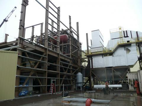
Boiler elements are supplied disassembled in the form of large-block components to be assembled directly on the customer's site. This procedure allows to minimize transportation costs (as oversize cargo carriage is avoided), as well as to avoid the use of heavy-duty lifting equipment (cranes), thus reducing the equipment installation cost as a whole.
Wellons boiler has a large-volume combustion chamber lined with refractory bricks, insulation and lagging. This volume of the chamber allows complete combustion of wet firewood, provides a low velocity of combustion products, significantly reduces the emissions of unburned particles and the formation of harmful combustion products (NOX, CO, etc.)
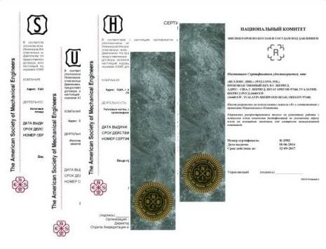
The boiler is designed and manufactured according to the stringent requirements of ASME regulatory documents (American Society of Mechanical Engineers) and certified by a company recognized by the Federal Service for Environmental, Technological, and Nuclear Supervision (Rostekhnadzor) of the Russian Federation.
2.1. PRELIMINARY DESIGN CRITERIA
Given below is a preliminary list of design parameters of the system described. Working capacity, pressure and temperature values are presented as measured at the outlet of the superheater.
- Capacity 120,000 kg/h
- Design pressure: up to 50 bar (gauge) *
- Working pressure: up to 40 bar (gauge)
- Steam temperature: up to 440°C
- Feedwater temperature: 110*C
* to be defined more precisely at the design stage.
2.2. BOILER – PRESSURE COMPONENTS
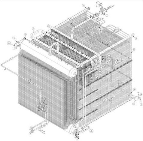
The boiler comprises steam drum, mud drum, headers, water screens, convection tube bank as well as steam superheater and attemperator system. The boiler water-tube section is designed for the necessary boiler performance and the required steam parameters (up to 65 bar and above). The large volume of the combustion/flue gas afterburner chamber allows to minimize emissions of harmful combustion products and large-size ash particles due to low gas velocities. The dependability of the boiler system is achieved by using boiler steel grades, including alloyed steel, with ASME certificated quality.
2.3. BOILER WATER-TUBE SYSTEM DESIGN
A certain design feature of the boiler water-tube system (screen headers are installed at a height of over four meters above the grate level) allows to avoid a sudden heat removal from the fuel by water tube system, wherea this heat is necessary to ensure the drying process in the event of a sharp increase of firewood dampness. This process is further facilitated by the construction of the boiler radiant section which, due to a special design of the rear rows of convection tube bank, allows to reflect the radiant energy of the flame directing it on the stack of fuel material and providing a fast drying and combustion of the firewood.
When assembled, the boiler water-tube system represents a large-volume chamber which ensures complete combustion of volatile gases produced in furnaces, while radiating energy to the boiler water screens, roof section, screen tubes and superheater section. The low velocity of combustion products, significantl reduces the exhaust of unburned particles and the formation of harmful combustion products (NOX, CO, etc.)
The water screens comprise a system of pipes connected at a certain interval to the lower and upper headers, which, in turn, are connected to the mud (lower) and the steam drums, respectively. The front screen tubes additionally form a "roof" of the boiler, their lower ends being connected to the header and their upper portions, while bending and forming an inclined surface, are attached directly to the steam drum. Generally, the boiler water-tube system is designed to provide the highest possible heat transfer and promotes the burning of firewood/bark and wood waste products with high moisture content and low calorific value.
2.4. BOILER SHELL AND INSULATION
The boiler tube system, including steam and mud drums, is lined and insulated with heat-insulating materials. The combination of heat-insulating materials and steel boiler casing provides an airtight system. Refractory and heat-insulating lining layer represents a multi-layered wall with a total thickness of 180-200 mm. 50-75 mm thick refractory bricks/tiles are used to build the first refractory layer. The refractory materials used has an on-load fusion point of at least 1200°C, which allows to protect the entire structure and ensure the service life of the boiler lining of up to 15 years or more. To reduce heat loss through the boiler body, two layers of thermal insulation material are applied, selected in view of the wall heat transfer parameter and the range of operating temperatures. Such multilayer wall structure ensures both a long repair-free service life of the lining and minimal loss of heat through the body, thus increasing the overall efficiency of the boiler. Unless otherwise specified, the refractory and heat insulating materials shall be an integral part of the delivery package.
2.5 SUPPORT STRUCTURES
Unless otherwise specified, all supporting elements of the boiler and its cladding, the metal structures of furnaces, air preheater, economizer, multicone header (multicyclone), ducts, buildings, catwalks, decks, fences, etc. shall constitute an integral part of the delivery package.
2.6. BOILER VALVES
The boiler shall be supplied complete with all applicable valves and auxiliary equipment necessary to ensure normal and technically safe operation of the boiler, including:
- safety valves;
- drain valves;
- vents;
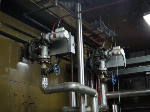
- shut-off and control valves and gate valves;
- samplers;
- chemical supply valve;
- drum and header blow-off valves;
- continuous blowdown valve;
- soot blower and superheater valves;
- pressure gauges and thermocouples;
- steam and feed water flow meters;
- water column and other devices, etc.
2.7. SOOTBLOWERS
In order to keep the heat transfer surfaces of the boiler water pipe system clean, thus ensuring a stable steam generation process in accordance with specified characteristics, different types of soot blowers working on According to a boiler model, 14-16 sootblowers may be installed. For example, in case of high-capacity boilers: up to ten rotary sootblowers are used for boiler convection banks; two retractable sootblowers – for superheater zone, one retractable sootblower – for removal of ash from the furnace bottom; and two sootblowers service the economizer system.
2.8. FEEDWATER CONTROL SYSTEM
This system comprises all the necessary flow sensors, pressure gauges, thermocouples as well as a variety of valves required to provide control and regulation of the direct water supply from feed pumps to the boiler steam drum.
3. FURNACE SYSTEM
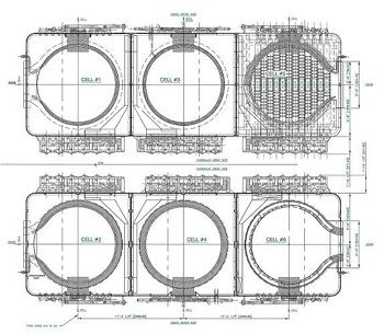
Cell-type furnace is specially designed for the disposal of various types of fuel/wood waste with a moisture content up to 70%. A system of multiple "ganged" furnaces allows to achieve a high single plant capacity of up to 120 MTH. We consider it necessary to further elaborate on all the features of the "Wellons, Inc." technology for burning wood fuel.
Ganged furnace system. The main distinction of Wellons systems from both the traditional shearing grates, and fluid-bed boilers comprises in a design feature providing for installation of one to six furnaces varying in size in one boiler. A wide selection of furnace dimensions allows us to construct boilers that satisfy most of the customers' requirements. Due to the fact that each furnace is equipped with individual power supply system, the impact of changes in fuel composition, whether in fractional makeup or humidity (fuel calorific capacity), is MINIMAL! The large number of furnaces (up to 6 pcs.) for one boiler prevents a simultaneous sharp drop in the thermal power of all furnaces in case of change in the percentage of fuel mixture components or increase of firewood humidity. This solution ensures process stability by timely change of combustion modes in other furnaces, leaving unchanged the total amount of heat required to produce steam. At the same time, the qualitative steam specification remains unchanged as well (because of the constant amount of heat). This control mechanism persists in case of lowering the fuel humidity and increase of its calorific efficiency. Timely change of combustion mode does not allow the combustion temperature to increase and prevents the premature failure of the lining (lining life reaches 10 years and more).
The proposed design comprising the installation of up to six burners on one boiler used in large-size boilers, allows a boiler work in the range of 20-105% of the rated load, as the system of ganged furnaces in Wellons boilers enables individual loading of the furnaces in proportion to the needs of steam consumers.
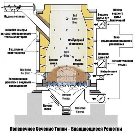
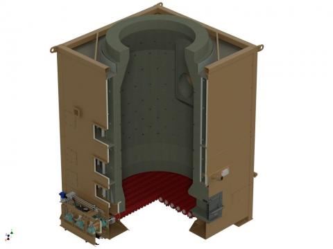
The furnace design. The figure below shows the principle schematic of an individual furnace design. It can be seen that Wellons furnaces employ a three-zone scheme of firing low-calorie wood fuel featuring its pre-gasification and subsequent burning of the gasification products in a boiler afterburning zone. The primary air is fed directly to the combustion zone, thus ensuring intense burning process of the fuel particles and high heat transfer. Tuyere holes in the furnace refractory lining, arranged tangentially at a certain angle (both vertically and horizontally), provide the primary air swirl within the furnace and ensure the maximum heat transfer, and the highest efficiency of the furnace and the boiler as a whole. Formation of vortex flows of combustion products and fuel particles inside the furnace ensures the completeness of combustion and prevents the carryover of unburned fuel particles and fine ash fractions to the convective section of the boiler.
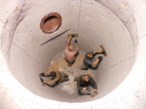
The boiler lining.The furnace of the boiler itself is lined with super duty, high-alumina refractories (Al2O3content >82%), with a load softening point equal to 1650-1700°C. Moreover, the use of these materials ensures resistance to high temperatures throughout the entire boiler system in the event of a sharp increase in the fuel calorific value (for example, due to a decrease in fuel humidity, or a change in its qualitative composition). Quite a large quantity of fire-resistant material (up to 30 tons per furnace) with a large heat capacity enables accumulation of a large amount of heat to be utilized for additional fuel drying in case of a sharp increase in its moisture content, or decrease of calorific value.
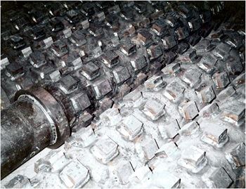
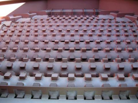
Fire grate.The attached photo demonstrates a fire grate after ten years of continuous operation. Such durability of grate shafts is achieved through the use of Wellons, Inc. know-how characterized in that the grate design provides 100% cooling of gear shafts working surface with water. The temperature of the entire shaft working surface is limited to the cooling water temperature which in turn is limited to a maximum temperature of 130°C.
The burning of the fuel layer occurs directly in the ash zone which not only provides protection to grates from high temperature zone, but, most importantly, is an inert layer, which when exposed to a large amount of pressurized air, forms a "suspended (fluidized) bed" on ash zone/fuel interface. This bed serves as a zone of direct heat exchange between the hot ash layer and moist fuel and, at the same time, ensures rapid drying and ignition of the fuel with the passage of the hot air at a temperature of up to 200°C through it. Since the weight of fuel is relatively low, the creation of a "suspended bed" at the ash zone/fuel interface does not require the use of power-consuming forced draft equipment.
The temperature of shaft grate working surface is limited to 130°C, therefore, the accumulation of slag (ash sintering) in our systems is minimal. Moreover, gear shaft grates while rotating in the opposite direction (towards each other), perform the function of a toothed roll crusher, destroying possible slag formation and removing them to ash removal section.
3.1 FUEL FEED AND DISTRIBUTION SYSTEM
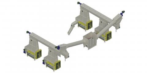
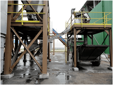
Receiving and distribution hoppers.Wood fuel is supplied to a distribution hopper located in the immediate proximity of the boiler via a main conveyor (not included in the scope of supply; optional). From the distribution hopper the fuel is moved, by means of two augers, to feed hoppers disposed on both sides of the boiler. Receiving/distribution hopper is equipped with the upper and lower level sensors which transmit signals to the main fuel conveyor and fuel storage bin in general (fuel storage bin is optional). All handling units (augers) are equipped with motors and drives, and removable covers for internal inspection and maintenance.
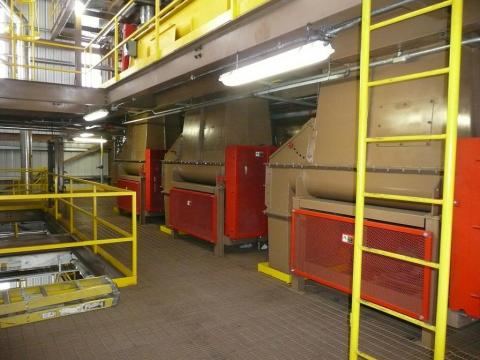
Metering feed hoppers.The supply package includes one metering feed hopper for each furnace. The metering feed hoppers located directly in front of the furnace control the supply of wood fuel into the combustion cell. The fuel level is constantly monitored by a level sensor. The fuel is fed to the cell feed auger in batches at an automatically controlled rate such that to maintain the desired level of fuel in the furnace and, accordingly, the pressure and flow rate of steam in the boiler. The supply package includes a variable-frequency AC drive to provide the precise speed control in a wide range.
Direct fuel infeed to boiler furnaces.To enable the delivery of fuel directly into the combustion chamber, each furnace feed hopper is equipped with a transverse auger running at a constant speed. Fuel is fed to the boiler for burning via a refractory lined chute. The fuel bunker auger feeding the boiler serves as a damper which prevents possible backflow of hot gases.
3.2. CELL TYPE FURNACE
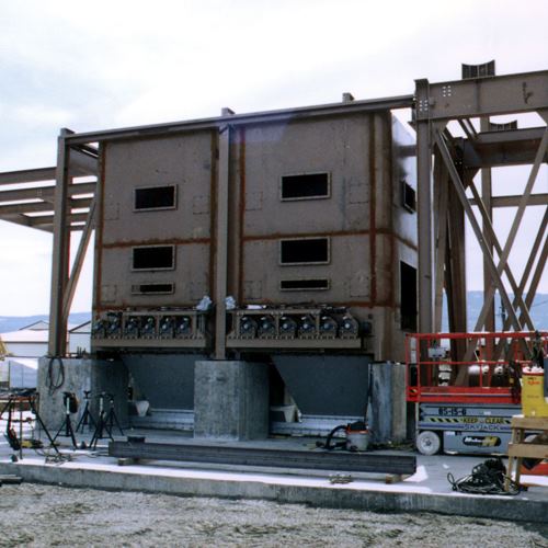
The scope of delivery for boilers with steam output of 120 MTH includes six furnaces with an inner diameter of 2,745 mm. The furnace represents a thermally insulated closed body ensuring minimum heat loss through its casing walls. The furnace is a single structure comprising the casing, the grate (with grate rolls), and the monolithic refractory lining that forms a cylindrical section of the combustion zone. Inside the furnace, between the housing and refractory lining there are airtight baffles, which divide the interior of the furnace cell into three zones. The air required for combustion passes through an air pre-heater and, heated to a temperature of 200°C, is distributed by zones of combustion, heading along the perimeter inside a steel casing. In turn, there are tuyere holes in the refractory lining, which serve primarily to feed the air directly into the fuel combustion zone to provide the swirling of combustion products and intense mixing of fuel and air, thus intensifying the combustion process. Formation of the gas stream on the principle of cyclone action prevents the carry-over of unburned fuel/dust particles and fly ash and accelerates to the utmost the process of moist fuel drying and combustion.
The boiler furnace is lined with super duty, high-alumina refractories (Al2O3content>82%), with a load softening point equal to 1650-1700°C. In addition, the tuyere holes positioned tangentially, ensure continuous cooling of the furnace walls, thereby increasing its service life. The service life of the refractory is 10 years or more.
Each furnace has a sight hole with heat-resistant glass for monitoring the combustion process, and is equipped with technological hatches with water-cooled doors for periodic inspection and cleaning if necessary.
3.3. ROTARY GRATES, FURNACE BOTTOM
Each furnace comes complete with a water-cooled rotary grate system which consists of pairs of rotary rolls, rotating about their axis toward each other. The grate rolls have "knobs" spaced at intervals allowing for the knobbed surfaces to pass by each other and to also provide space for passage of primary combustion air. The grate rolls are assembled in pairs and can rotate in either direction.
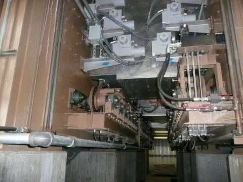
At timed intervals, each pair of rolls rotate, crushing the ash and slag deposits between them, and dropping it to a conveyor below. These rolls are hydraulically powered by an indexing, ratcheting mechanism. The hydraulic drive system of this mechanism is equipped with load limits to protect the grate rolls from overload ( for example, when a piece of metal falls on the grate), wherein the pair of knobbed rolls suffering the overload may be reversed.
The grate rolls are made of high-alloy, heat-resistant steel. At the same time, the internal design provides 100% water-cooling of the entire grate surface. This allows to avoid heating of the grate surface above 130°C. The cooling water, heated in passing through a grate is routed to a deaerator to be further used in the steam production process. The recycling of grate cooling water for subsequent utilization in steam production increases an overall boiler efficiency.
The boiler supply package includes a hydraulic drive specifically designed for the operation of the knobbed rotary grate rolls.
4. COMBUSTION AIR SYSTEM
Warm air is drawn from the upper level of the boiler house building, through ducting, to a forced draft fan. Then, air is ducted through the combustion air preheater and, when heated to 200°C, is distributed among combustion zones. A system of slide damper automatic control provides the required amounts of combustion air to each combustion zone depending on the boiler operating mode and fuel condition at any given time. This system, being an integral part of the overall fuel combustion control system, controls the supply of air depending on specific formulations that are in turn dependent on the fuel humidity. Continuous monitoring of combustion air pressures in all furnace zones, whether in undergrate or over-fire space, gives assurance of the optimal firing balance at all times.
4.1 FORCED DRAFT FAN
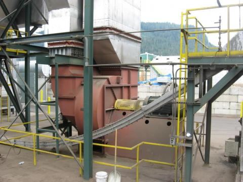
A centrifugal forced draft fan is used to supply air amounts required for fuel pre-drying and maintenance of normal fuel combustion process. The forced draft fan is driven by a totally enclosed fan-cooled electric motor. The fan provides warm air intake from the upper level of the boiler house building, its passage through the air pre-heater and supply to the combustion zone via the air supply and distribution ducting as described in Section 4. It is an integral part of Wellons delivery package.
4.2. COMBUSTION AIR DUCTING
Air ducting is manufactured with 6 mm gauge steel and insulated with 75 mm of 370°C mineral wool. Additionally, the insulated ducting is weather protected with a 0.8 mm thick aluminum cover. Air ducting and insulation are included in the equipment scope of supply, therefore, their cost is incorporated in the offer quotation.
5. EXHAUST GAS SYSTEM
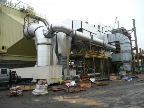
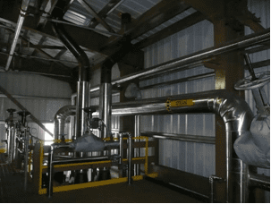
Due to a negative pressure maintained by induced draft fan, combustion products and excess air, passing through an economizer, combustion air pre-heater, dust removal/multiple cone collector system give excess heat to feedwater and combustion air, thereby increasing the overall efficiency of the plant. All of these units are connected with flue gas ducts. The flue gas temperature is always above the dew point of at least 160°C. A set of equipment necessary for removing and cleaning flue gases to 200 mg/Nm3 is an integral part of the delivery.
Optionally, it is proposed to install an electrostatic precipitator (electrostatic filter) which reduces the level of dust emissions to 50 mg/Nm3. Upon request, the equipment may be included in the scope of supply.
5.1. ECONOMIZER
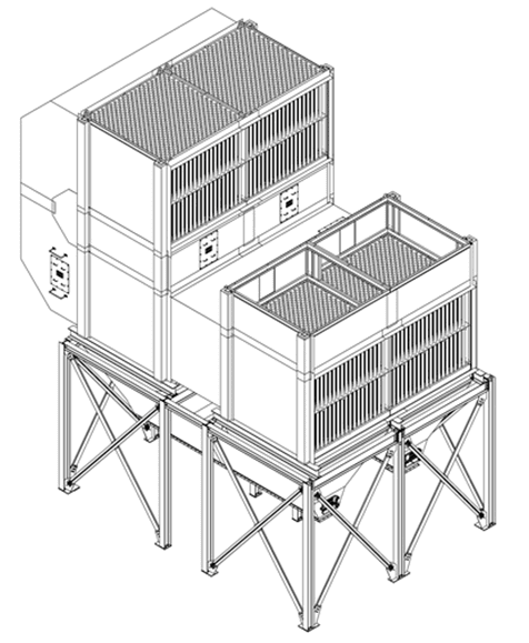
A factory-assembled economizer is furnished to recover excess heat in boiler exhaust gases for increasing temperature of feedwater prior to entry into the boiler steam drum.
The economizer is furnished with rotary sootblowers, access man-ways, thermocouples, pressure sensors and safety relief valves. The unit is insulated and jacketed for weather protection. The economizer gas inlets and outlets are flanged for connection to exhaust gas duct sections. Also, the economizer is furnished with drain valves to permit maintenance during shutdown periods. It is an integral part of Wellons delivery package.
5.2 COMBUSTION AIR PRE-HEATER
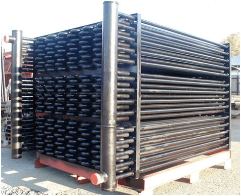
An air pre-heater is installed on the boiler exhaust in the direction of the gas flow to provide heat exchange between flue gases and combustion air (via pipes). It consists of 76 mm vertical tubes which allow to raise primary combustion air temperature to 200°C and cool the exhaust gas (to a temperature not lower than the dew point of ~ 160°C), increasing the overall efficiency of the system.
Access is provided at top and bottom of the heat exchanger for ease of inspection and cleaning (when necessary). Outside surfaces are fully insulated with 75 mm thick mineral wool and weather protected with a 0.8 mm thick aluminum cover. Heat exchanger bypass is included for stack temperature control during extended periods of low firing rates and start-up. Combustion air pre-heater is an integral part of Wellons delivery package.
5.3. MULTIPLE CONE COLLECTOR
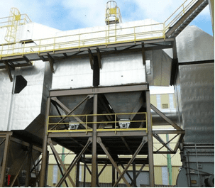
The boiler system is provided with a multiple cone collector/multicyclone with 230 mm diameter cast tubes and a cast conical section of wear-resistant material. It is located along the gas flow downstream from the combustion air pre-heater. Entrained dust particles and ash from exhaust gases is efficiently removed and deposited in the lower hopper section of the multiple cone collector. The dust accumulating in the hopper is then removed by built-in augers through a rotary air lock valve onto a common ash removal conveyor. The use of multiple cone collector allows reducing the emission of dust particles to a concentration of not more than 200 mg/Nm3.
Access door is provided in the multiple cone collector for inspection and cleaning. Outside surfaces are fully insulated with 75 mm thick mineral wool and weather protected with a 0.8 mm thick aluminum cover. It is an integral part of Wellons delivery package.
5.4. EXHAUST GAS DUCTING.
All ductwork (similar to combustion air ducting) is manufactured in large units with matching flanges, pilot drilled for assembly on customer's site. Exhaust gas ducts are fully insulated with 75 mm thick mineral wool and weather protected with a 0.8 mm thick aluminum cover. Exhaust gas ducts are an integral part of Wellons delivery package.
5.5. INDUCED DRAFT FAN
An induced draft fan maintains a constant negative pressure in the furnace, drawing the combustion gases through the exhaust gas ducting. Draft control is automatically maintained with an electric actuator, operating a damper immediately ahead of the I.D. fan. It is an integral part of Wellons delivery package.
6. COMPUTERIZED CONTROL SYSTEM
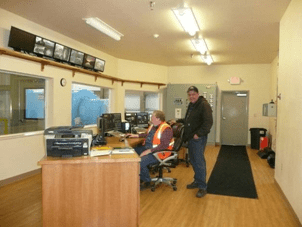
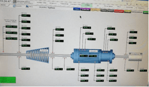
Boiler unit is controlled via a host computer by means of multiple monitors, which display all parameters of steam production process, as well as the equipment mimic with characteristics of main and auxiliary equipment. At the customer's request, the software can be developed for METSO, Siemens, Alan Bradley or other platforms. All messages displayed on monitors are Russified, and computer control system is designed to be easy to learn, simple in operation and service.
System components
Computer control system consists of the following equipment (or its equivalent):
- HP Compaq Business Desktop dc7600;
- A 56k external fax modem;
- Two 17" monitors ADI5P+;
- A color printer;
- Uninterruptible power supply
- Wellons Control System software package.
Control functions.
The computer system controls, and issues reports on the following parameters of the boiler system:
- Fuel delivery rate;
- Forced draft fan operation;
- Induced draft fan operation;
- Master Control Function, which automatically controls fuel supply and forced draft fan control under various boiler house operating conditions;
- Feedwater pumps;
- Condensate return;
- Gratewater pumps;
- Tuning screens for all process controls;
- Steam volume metering for steam pressure recording.
- Trending and Recording
- Steam flow;
- Steam pressure;
- Daily totalized steam production;
- Boiler drum level;
- Fuel consumption data, etc.
Safety features:
- Automatic plant shutdown on low water alarm;
- Automatic plant shutdown on failure of induced draft fan by power interruption or other;
Audible and visual alarms including:
- Boiler water level low;
- Induced draft pressure low;
- Feedwater tank level low;
- Fuel System trouble;
- Steam pressure low;
- Motor operation fault;
- Individual manual over-ride controls are supplied with a master relay to shut down the entire plant.
7. AUXILIARY EQUIPMENT
Listed below is the auxiliary equipment required for the boiler plant normal operation. Unless otherwise specified, this auxiliary equipment is provided by Wellons.
7.1. CONTROL PANELS
A separate pre-wired control cabinet is furnished and contains relays and related controls for automatic operations, along with an over-ride relay and stop button to shut down the entire plant.
7.2. DEAERATOR
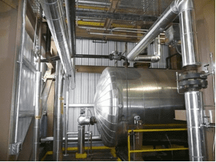
Deaerator is used in the boiler house to remove corrosion-aggressive gases, oxygen and free carbon dioxide (O2 и CO2) from the feed water treatment system. The non-condensable gases are released to the atmosphere through a vent condenser. The unit consists of the following:
- Horizontal tank for feedwater storage;
- Overflow trap;
- Pneumatic level controller with diaphragm regulating valve for cold water make-up;
- Steam pressure relief valve;
- Pressure gauges and thermometers.
7.3. FEEDWATER PUMPS
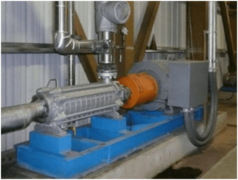
Multistage high-pressure pumps are designed to increase the water pressure to a preset value and provide its supply to the boiler water-tube system (boiler steam drum). Two boiler feed pumps are provided, one pump designed to operate at full load under a preset operating pressure. Both pumps are motor-driven.
A back-pressure valve and a three-way recirculation valve are incorporated into the pumping assembly piping. In addition, the pumps shall be connected to the customer's emergency power system.
7.4. GRATEWATER PUMPS
Single-stage medium pressure centrifugal pumps are procured. These pumps are designed to supply water to grate roll system for cooling cell grates. The pumps transfer cooling water from deaerator to the grate roll system to prevent heating of the grate working surface above 130°C. Water, passing through the grates, is further heated and returns to the deaerator, thus increasing the overall efficiency of the plant. Two pumping units complete with motor drive are provided. Each pump performance is designed for a full load at preset operating parameters of the cooling system.
7.5. WATER TREATMENT
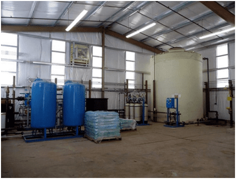
Optional equipment. Water treatment system is intended to maintain a preset chemical and mineral composition of the feed water for the normal operation of the boiler water tube system, preventing the deposition of salts on the heated inner surfaces and corrosion of the water tubes. Two demineralizing systems will be furnished to remove dissolved minerals from raw water supplied. The delivery includes:
- Duplexdemineralizer;
- Flow meters;
- Set of regenerant consumption indicators;
- Low flowrate circulation pumps;
- Sulphonate and caustic injection pump;
- Caustic storage tank and mixer;
- pH adjustor;
- neutralized water tank for two regeneration systems with feed pump and a control system.
7.6. CHEMICAL INJECTION EQUIPMENT
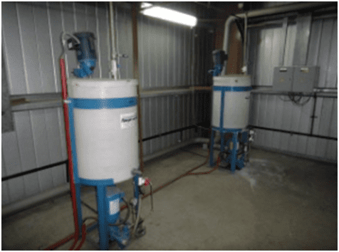
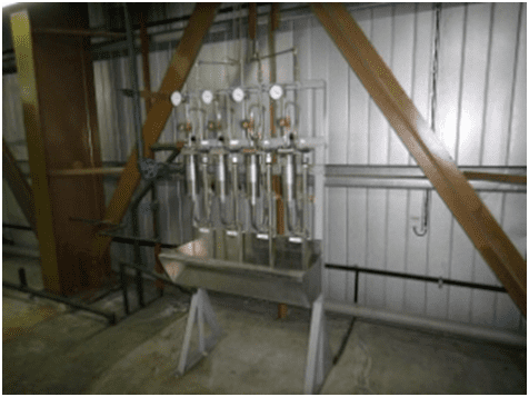
It is designed for injection of agents required to adjust the chemical composition of the feed water, as well as for system chemical cleaning. Chemical injection system comprising chemical solution tank with mixer and injection pump. Additionally, sampling station with a testing equipment is also supplied.
7.7. BLOWDOWN HEAT EXCHANGER
A blowdown receiver is provided to separate the flash steam from the blowdown discharge. The flash steam is routed to deaerator to recover energy for increasing feedwater temperature, while the blowdown discharge is passed through the heat exchanger shell and tube to recover heat for chemically purified water.
7.8. BOILER SYSTEM PIPING
All piping for the systems (water, steam, condensate, etc.) located within the limits of the boiler house (battery limit is 1 m from the walls of the building) is procured in full. Pipe, pipe supports and insulation are provided to complete the following piping systems:
- Process condensate return piping from battery limit to water treatment system;
- Deaerator to feedwater pumps to boiler steam drum inlet flange;
- Gratewater piping from deaerator to gratewater pumps and from furnace grates to deaerator;
- Steam and air sample piping from extraction ports to control panels;
- Steam piping from boiler outlet flange to battery limit,
- etc.
7.9. ASH REMOVAL SYSTEM
The heavy ash deposits accumulated on furnace cell water-cooled grates are automatically discharged by grate rolls rotating at preset intervals. The auger located at the bottom of the ash hopper transports the ash to the main ash conveyor (chain scraper conveyor). This conveyor also collects the ash from the boiler (convection bank), combustion air pre-heater and multiple cone collector. Ash from the main ash conveyor is dropped into an ash receiving bin outside the boiler house building (replaceable ash bin is optional.)
7.10. AIR COMPRESSOR
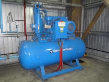
Designed to provide compressed air for valve control systems and other pneumatically driven mechanisms. The compressor is supplied to ensure operation of these mechanisms independent of in-house compressed air system. Air compressor capacity is at least 1 m3/min of air at 7 bar pressure. The system also includes a storage tank and an electric motor.
7.11. BOILER HOUSE BUILDING. CATWALKS AND LADDERS
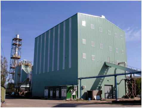
A fully equipped building including steel frames with enclosures using sandwich panels as wall and roof metal siding.
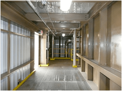
The boiler house building has windows, doors and gates as required by labor and health safety regulations. A choice of standard colors is offered for external cladding. Catwalks, floors and access platforms are provided as required by boiler operation and maintenance regulations. These are fabricated of rolled steel with max. design live load of 245 kg/m2. Ladders, stairs, railings are included, as necessary to ensure access to the equipment and its normal operation.
7.12. ELECTRIC MOTORS AND SWITCHBOARDS
All motors which are a part of the boiler equipment are procured by Wellons. All motors controls, protection devices, as well as the main and auxiliary circuit breakers are supplied by Wellons.
8. PRICE AND STANDARD DELIVERY TERMS
Price quotations are based on the current level of prices for materials and work. The estimated cost of the offer can vary within the range of ± 5% of the final price provided that no changes are made in the design or the scope of delivery.
8.1. PRICE
Prices are specified in a separate commercial offer and are subject to contract negotiations.
8.2. DELIVERY TERMS
All delivery prices are DDP.
8.3. STANDARD TERMS OF PAYMENT
- 50% payable upon signing the contract
- 40% to be paid by equal installments, according to a main component shipment schedule to be agreed upon by the parties.
- 10% to be paid within 72 hours (according to the rules of Rostekhnadzor) after completion of technological tests provided that set parameters are achieved.
The final terms of payment are subject to contract negotiations.
8.4. STANDARD WARRANTY
Wellons equipment is subject to warranty period of 24 months from the date of the equipment commissioning. The system is guaranteed to work in accordance with the specifications of the contract, provided that the Buyer complies with all the requirements to fuel, power supply, etc.
9. COMPLETENESS OF EQUIPMENT
DESCRIPTION | VENDOR | CUSTOMER | OPTION |
9.1. BOILER | |||
| Pressure vessels | x | - | - |
| Superheater | x | - | - |
| Boiler auxiliary devices | x | - | - |
| Pressure safety valves | x | - | - |
| Boiler shell and heat insulation | x | - | - |
| Boiler supports | x | - | - |
| Feedwater control system | x | - | - |
9.2. FURNACE | |||
| Furnace system | x | - | - |
| Fuel feed to furnace | x | - | - |
| Furnace refractory lining and heat insulation | х | - | - |
9.3. AIR SUPPLY | |||
| Forced draft fan | x | - | - |
| Combustion air ducting | x | - | - |
| Air ducting insulation | х | - | - |
9.4. FLUE GAS SYSTEM | |||
| Economizer | x | - | - |
| Combustion air pre-heater | x | - | - |
| Multiple cone collector | x | - | - |
| Exhaust gas system | x | - | - |
| Exhaust ducting insulation | х | - | - |
| Induced draft fan | x | - | - |
| Exhaust stack* | х | х | |
| Electrostatic precipitator with exhaust stack* | х | x | |
9.5. CONTROL SYSTEM | |||
| Computerized boiler control system | x | - | - |
| Control I/O system | x | - | - |
| Control interface | x | - | - |
| Control devices, etc. | x | - | - |
9.6. ANCILLARY EQUIPMENT | |||
| Control cabinet | x | - | |
| Feedwater pumps | x | - | |
| Grate cooling-water pumps | x | - | |
| Deaerator | x | - | |
| Chemical water treatment system | х | х | |
| Chemical injection system | x | - | |
| Purge air system | x | - | |
| Boiler trim piping | х | - | |
| Ash removal system | x | - | |
| Ash removal bins (replaceable) | x | х | |
| Air compressor | x | ||
| Standalone boiler house building | х | ||
| Boiler control room | x | ||
| Motor control center room | x | - | |
| Ladders, platforms, catwalks | x | - | |
| Electric motors and switchgear | x | - | |
| Fuel bunker* | х | х | |
| Main fuel conveyor* | х | х | |
10. SERVICES
DESCRIPTION | VENDOR | CUSTOMER | OPTION |
| Design and engineering | x | ||
| Technical documentation and drawings | x | ||
| Foundation load presentation | х | ||
| Calculation of equipment foundations and construction work | x | ||
| Mechanical equipment installation | x | ||
| Power supply calculation and installation work | x | ||
| Technical support for installation and commissioning | х | ||
| Equipment loading to containers | x | ||
| Freight* | х | x | |
| Utility connections (water supply, power, telephone communications and Internet)* | x | х | |
| Lighting (internal and external)* | x | х | |
| Heating* | x | х | |
| Drainage systems (internal and external)* | x | х | |
| Fuel delivery to furnace distribution conveyor* | - | x | х |
| Chemicals and lubricants | - | x | - |
| Fire-fighting system* | - | x | х |
11. DIVISION OF RESPONSIBILITY
| Raw water | Along the building wall |
| Fuel feed | Fuel storage bin inlet |
| Power | On indoor switchboard |
| Steam supply | Along the building wall |
| Condensate return | Along the building wall |
| Telephone, Internet | In Control room |
| Ash | Ash conveyor outlet |
12. TECHNICAL SECTION
12.1. BOILER HOUSE PARAMETERS | |
| Continuous full load | CFL |
| Maximum steam output1 | 120 MTH (CFL) |
| Rated heat output | 95 000 MWH (CFL) |
| Rated steam pressure2 | up to 40 bar (gauge) |
| Rated steam temperature2 | up to 440°C |
| Feedwater temperature: | 110°C |
| Feedwater flowrate: | ~ 122,000 kg/h |
| Internal consumption3 | no more than >2% of steam output |
| Operating range4 | 30% to 100% |
| Power input in kW5 | 1,750 kW |
Notesto section 12.1: 1 According to values measured at the steam superheater outlet; 2 The parameters mentioned above are given as typical. Other steam parameters can be calculated on customer's request. 3 Given steam consumption rate refers to steam heating for deaerator and/or feedwater turbine pump; 4 The boiler may operate at 15% of the maximum rated power (on good fuel), but the temperature of the steam decreases by half of the nominal value. The steam pressure will remain constant in the range of 15-100%; 5 Empirical data obtained from previous projects. At the design steam output, workloads make up approx. 80% of the input load value. | |
12.2. FUEL PARAMETERS | |
| Nominal gross calorific value (completely dry fuel) | 4,800 kcal/kg |
| Nominal humidity (on wet basis) | 55% |
| Low heat combustion value | ~ 1,700 kcal/kg |
| Expected fuel consumption by weight | ~ 55,000 kg/h |
| Expected fuel consumption by volume (bulk density approx. 320 kg/m3) | ~ 170 m3/h |
| Expected ash content (based on the weight of oven-dry fuel) | 2% |
| Note: Fuel parameters mentioned above are given as typical. | |
13. ADDITIONAL INFORMATION
13.1. PERSONNEL:
Usually 2 operators per shift and one shift supervisor. Mechanics and electricians may be invited from other departments if required.
13.2. SYSTEM COMPLEXITY:
The mechanical equipment is very easy to operate and maintain. Computerized ACS. Basic computer knowledge is sufficient to manage the entire complex.
13.3. CONSUMABLES:
A small amount of oil and grease, water treatment chemicals are necessary, as usual for a boiler.
13.4. OVERHAUL PERIOD:
If the system is operated as instructed, no overhaul repair will be required. Some boiler components such as multiple cone collector, refractory lining may suffer a slight wear-off.
13.5. SERVICE LIFE:
Usually no less than 40 years.
13.6. SERVICES OR EQUIPMENT
Necessary, but not included in the Wellons scope of delivery:
- Construction machinery
- Calculation of foundations, foundation casting
- Mechanical installation work (including any consumables)
- Cabling and cable trays
- Electrical design and installation.
- Any piping beyond the Wellons battery limit
- Lighting (internal and external), heating, site preparation and planting.
- Permits (except those issued by Wellons).
- Emissions metering equipment and fire extinguishing system (if necessary).
- Other services and equipment not included in the Wellons scope of delivery
13.7. STANDARD PROJECT SCHEDULE
Delivery of equipment: no later than 14 months from the date of receipt of payment. Start of equipment shipping: in 6 months. Commencement of installation works: in 6 months from the start of equipment arrival. Equipment commissioning: in 18 months.
We hope that this technical proposal contains all the information necessary for you to make a decision on further cooperation. We are ready to answer any questions which may arise as soon as possible.
