ENGINEERING.
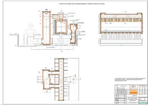
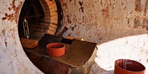
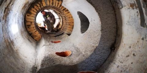
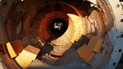
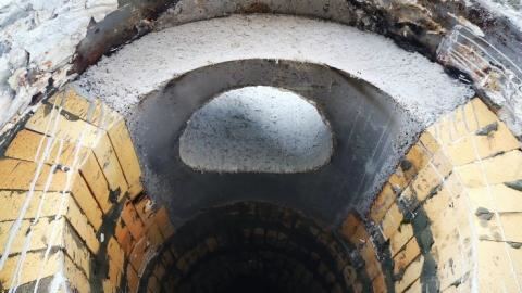
Within this project, the Wellons.RU LLC specialists have developed in the shortest possible time various refractory options with a single-layer and two-layer installation, taking into account the equipment design features, including the possibility of technical/process use of various types of refractory and insulation materials (brick, plates, blanket material), and also monolithic refractories (concrete). The combination of different types of refractories (brick, concrete) allowed us to provide a ready-made solution to this complex project that fully meets customer's requirements for the specifications of the refractories used and within the allocated budget.
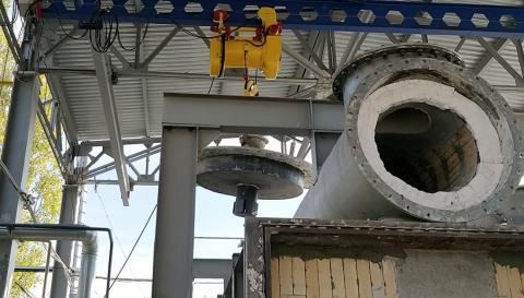
The complexity of this project is due to the equipment design features, the small size of its various parts (for example, the header and gas ducts diameter is from 800 to 1,000 mm, and the length of these sections exceeds 8 meters), a flat roof, which in turn requires suspended bricks, and different diameters of the process equipment shells — the required products were made according to customized drawings.
At the customer's request, our company prepared a plan of organization of work (POW) at the facility and a refractory installation project with explanatory note. The whole package of technical documentation was delivered in *.dwg format to the customer specialists for further use. Part of the working drawings for this project is presented in the section ENGINEERING on our company web-site.
REFRACTORY SELECTION AND SUPPLY
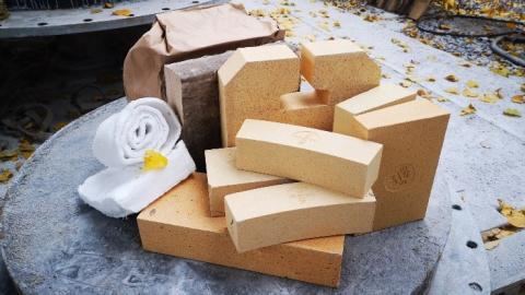
Due to the process equipment complex design and a large number of transition sections present (interface of two or more gas ducts of different diameters, circular sections and flat surfaces, conical transition sections, various end covers of equipment, etc.) we had, in addition to selection of a refractory products range basing on the existing brick sizes as per GOST 8691-73, to develop individual drawings with making a special order to the manufacturer on insulating curved brick basing on different equipment diameters.
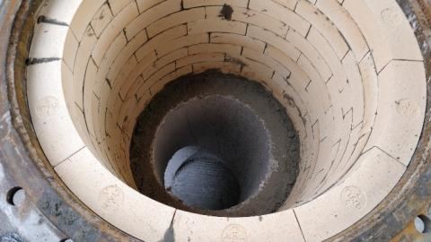
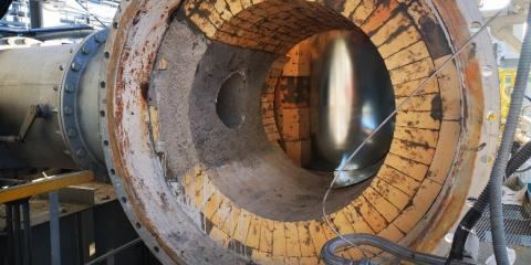
The use of appropriate products (double-sided neck brick), as well as their various combinations, made it possible to ensure the most correct geometry (circumference) in the refractory of cyclone furnace, header of destruction furnace. The refractory concrete use enabled the most reliable construction of transition sections refractory (interface of the furnace flat roof and top header pipes, furnace bottom, header covers and the cyclone furnace, as well as the newly installed furnace extension). The insulating materials (kaolin plate and blanket material) used with the refractory bricks and concrete enabled minimum thermal conductivity of a two-layer wall. The blanket material (6 and 38 mm thick) is used for the expansion joints compensating various heat expansions of steel and refractory materials, primarily the refractory concrete. An aluminosilicate mortal MSh-28 is used as a masonry mortar with a mixture of chemical hardener and water as a mixing solution. This type of masonry mortar enables initial hardening of the refractory masonry mortar during refractory installation, even before the refractory drying starts.
The combined use of the above materials allowed us to complete the project on polymer wastes incinerator refractory two weeks ahead of the agreed time.
INSTALLATION
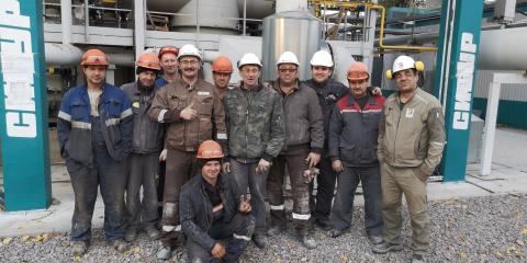
All the works related to refractory installation were directly supervised by Wellons.Ru LLC specialists. Specialists of SinthezMontazh LLC, within our EPC contract, installed the refractory and performed necessary auxiliary works.
All the main types of work are described below in the relevant sections. You can see it also in our brief video in the section "POLYMER WASTES INCINERATOR REFRACTORY REPLACEMENT PROJECT".
1. FURNACE EXTENSION (newly installed)
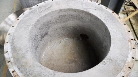
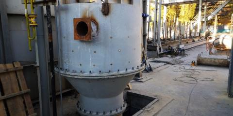
The design of the refractory of the furnace extension and gas duct to the bottom header is two-layer with curved insulation bricks of various sizes, made according to individual drawings for each diameter of the structure: furnace, transition cone and gas duct.
FURNACE EXTENSION TOP PART (cylindrical) – the refractory is two-layer with a total thickness of 215 mm — the insulation layer — 65 mm, the working layer thickness is 150 mm. The stages of work are presented below:
Bottom:
- Before the insulation layer installation start, anchors are installed to secure fixing of refractory concreting working layer.
- Insulating brick is laid in the inter-anchor space (using masonry mortar), as closely as possible with the brick adjustment. Existing seams are filled with mortar.
- After the insulation layer installation, steel anchors are bent perpendicular to each other, to ensure the strongest possible concrete fixing.
- After installation of anchors and insulating layer, the curved brick is laid to minimal 150 mm height.
- Then refractory concrete layer is casted. The layer thickness is 150 mm.
Walls:
- Three layers of curved brick are installed on the shell of the furnace extension cylindrical part.
- Anchors are installed with an interval of 250 mm and the insulation layer installation continues. If necessary, insulating curved brick is cut at the points of the anchors attachment to the shell.
- Bricklaying and anchors installation are continued according to the procedure described above.
- When insulating layer installation is finished, the blanket insulating material is glued on the furnace extension bottom and on the burner nozzle to made expansion joints.
- Formwork is installed and refractory is concreted using an immersion vibrator to distribute the concrete over the entire area and compact it.
- After the concrete curing the formwork is removed.
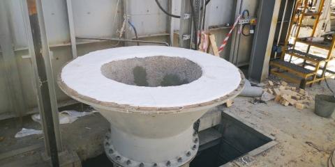
Transition cone of the furnace extension - the refractory is two-layer with a total thickness of 215 mm — the insulation layer — 65 mm, the working layer thickness is 150 mm. The stages of work are presented below:
- The methods of installation of insulation layer, working layer, including installation of anchors and formwork are similar to the installation methods described in the section above (the furnace extension refractory).
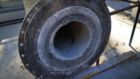
FURNACE EXTENSION GAS DUCT (newly installed) - two-layer refractory with a total thickness of 180 mm — the insulation layer — 65 mm, the working layer thickness is 115 mm. The complexity of the design of the gas duct is related to its size (diameter — 800 mm, length — 2,100 mm) with transition pipe tie-in, as well as the need for a two-layer refractory due to the gas flow high temperature (up to 1,200°C) and provides two stage refractory installation. The stages of work are presented below:
First stage:
- Gas duct bottom refractory with installation of the insulating brick layer.
- Installation of the insulating curved brick layer to the height of the refractory working layer on the gas duct shell.
- 140–150 mm thick gas duct bottom working layer refractory concrete casting.
- Nozzle/square elbow refractory with a curved insulating brick.
- Installation of internal formwork (complex joint formwork of the elbow vertical and horizontal part interface).
- Working layer casting with refractory concrete to a height of ~ 1,000 mm.
- Disassembly of the first stage formwork (after the concrete curing and achieving the required strength).
Second stage:
- Installation of the insulating curved brick to gas duct end (to the flange connection).
- Installation of the blanket insulating material for the formation of the expansion joints along the border of the first stage concrete casting.
- Installation of internal formwork to a height (~ 1,000 mm) for working layer casting. The layer thickness is 115 mm.
- Disassembly of the second stage formwork (after the concrete curing and achieving the required strength).
Upon completion of work, the connecting flanges of all parts of the equipment were cleaned and prepared for assembly/installation at the installation site.
2. THERMAL DESTRUCTION FURNACE
For thermal destruction furnace refractory various types of insulating and refractory materials were combined, namely:
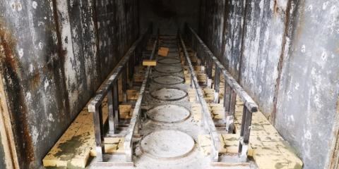
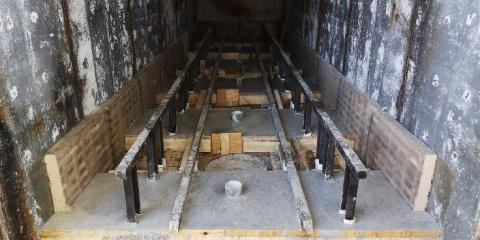
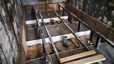
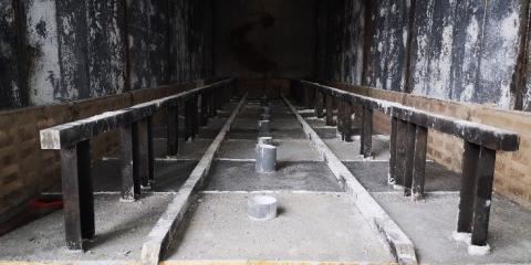
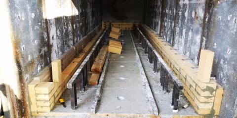
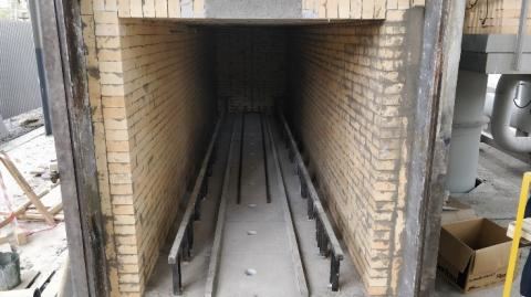
The furnace/chamber bottom – the refractory is two-layer. 150 mm thick refractory concrete working layer, 65 mm tile/brick insulating layer. The refractory total thickness is 215 mm. The stages of work are presented below:
- 65 mm thick insulation layer — due to the need to ensure the strength of the structure, ShTU-1.3 brick is used as the insulation material. Prior to bricklaying the surface is cleaned of foreign particles and dirt. The masonry mortar on the basis of chamotte mortal MSh-28 is used for bricklaying.
- The insulating layer for the interface of the furnace bottom and its walls is made using a KTP-65 kaolin plate. This material is laid before the furnace bottom monolithic refractory working layer concreting to ensure insulation throughout the cross section of the refractory wall. The kaolin plate is laid with masonry mortar based on MSh-28 chamotte mortal and chemical hardener.
- The metal racks of the mobile cart rail as well as the cart movable platform supports are glued over with blanket insulating material prior to refractory concreting. This material is necessary to compensate the difference between steel and concrete heat expansions.
- The polypropylene pipes of the required diameter are used as fixed formwork for the formation of the gas ducts inlet from the bottom header to the destruction chamber.
- Formwork design — the formwork is installed in such a way as to ensure the casting of refractory concrete with casting sequences of a certain size. The formwork design should provide the possibility of its disassembling into the interior of non-filled casting sequences, without destroying the cast concrete.
- The concreting of the working layer is carried out by casting sequences with expansion joints application. After concreting and curing, and accordingly, after formwork disassembling, the blanket insulating material is laid on the sides of the filled casting sequences, to compensate the heat expansion of the monolithic refractory.
- Upon expansion joints completion the remaining casting sequences (formed between the previously filled casting sequences) are concreted.
Destruction furnace/chamber walls – the refractory is two-layer. Working layer — 150 mm thick refractory brick ShA-10, insulation layer — 65 mm thick KTP-65 kaolin plate. The refractory total thickness is 215 mm. The stages of work are presented below:
- Insulation layer — the kaolin plate KTP-65 is glued over furnace body walls with masonry mortar based on MSh-28 chamotte mortal.
- The working layer — bound together aluminosilicate bricklaying ShA-10 with masonry mortar.
- When bricklaying reaches the level of insulating plate (~ every 500 mm), the steel heat-resistant T-shaped anchors (flat, 2 mm thick) are installed to provide a more rigid structure of the furnace walls and prevent destruction of the masonry during operation.
- After installation of the anchors, the next row of insulating plates is mounted, accordingly, the refractory brick is laid to the level of the insulating plate (with ~ 500 mm interval).
- The anchors, insulation and refractory materials installation procedure is repeated to the level of roof suspended brick.
- The anchors are installed around the whole furnace perimeter with ~ 350 mm step.
- The insulation plate at the furnace edge, at the furnace door, is covered with refractory bricks to ensure the necessary strength of the wall masonry in the area of the opening/closing zone.
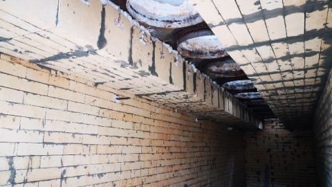
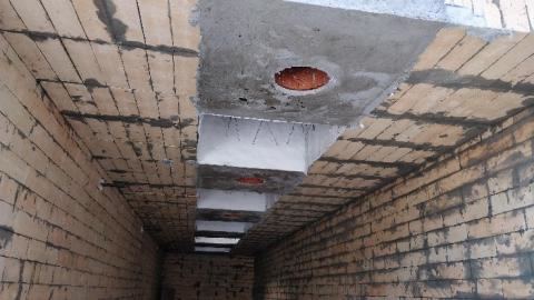
The destruction furnace/chamber roof, the suspended roof – are made of 300 mm suspended brick and 30 mm thick insulating blanket material. The total thickness of the refractory layer is 330 mm. The stages of work are presented below:
- Suspension elements (tee bars) are welded to the body (to the roof) before installing the suspended brick/blocks. These suspension elements are installed with certain step (~ 290 mm) to ensure maximum density of rows.
- Suspended brick ShA-83 is hung with a frog on the suspension element. The surface of the brick is covered with masonry mortar and the subsequent brick, when it is suspended, is pressed tightly to the previous brick. The thickness of the seam between the transverse rows, if possible, is regulated by moving the brick on the suspension element.
- In parallel with suspended brickwork, the space between the brick and the chamber roof is filled with blanket insulating material.
- Brick laying is carried out in two directions from the top header gas ducts to the furnace walls.
- Two extreme rows of suspended bricks, both on the one and on the other hand, are sized, for the closest interface of the wall and roof bricks, respectively.
- The space between the furnace body and the first longitudinal row of suspended bricks is filled with insulating material (kaolin plate and blanket material).
The destruction furnace/chamber roof, zone of transition gas ducts of the top header - the monolithic refractory:
- The anchors of refractory concrete fixing are welded before the formwork installation.
- The surface of the suspended brick within the casting sequences boundaries is glued over with blanket insulating material to form expansion joints and compensate the concrete and refractory bricks heat expansion.
- After anchors installation, expansion joints formation, the roof and top header gas ducts transition section casting sequences formwork is installed.
- A 200 mm diameter polypropylene pipe is used as a fixed formwork for the gas ducts holes formation.
- The concreting is performed through the top header using vibrator to ensure uniform concrete filling of the casting sequence entire area and its compaction.
- After the concrete curing, the formwork is disassembled and the non-filled casting sequences are prepared for concreting.
- Formed "empty" casting sequences are glued over the total perimeter (all four sides) with insulating material.
- Further preparation of the formwork and the concreting are performed similarly to the above mentioned procedure.
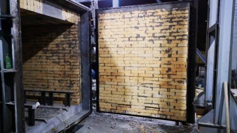
Destruction furnace/chamber door - the refractory is two-layer. Working layer — 150 mm thick refractory brick ShA-10, insulation layer — 65 mm thick KTP-65 kaolin plate. The refractory total thickness is 215 mm.
- Prior to refractory, the supporting elements of the door (box) for refractory installation were manufactured and welded.
- The metal frame is reinforced with stiffeners installed evenly around the perimeter of the frame.
- Insulation layer — the kaolin plate KTP-65 is glued to the door body with masonry mortar based on MSh-28 chamotte mortal.
- The working layer — bound together aluminosilicate bricklaying ShA-10 with masonry mortar.
- For the formation of an expansion joint, the blanket insulating material is glued to the inside of the metal frame.
- The door refractory, the refractory anchors are installed similarly to the procedure described in the section of the thermal destruction chamber refractory installation.
3. THERMAL DESTRUCTION FURNACE TOP HEADER
A large number of different interfacing surfaces (vertical transition sections of gas ducts into the destruction chamber, two explosion relief valves of the top header, two gas ducts to the cyclone furnace), as well as the gas ducts small diameter (from 500 mm to 1000 mm), make the refractory of this section one of the most difficult for this project. To solve the refractory issues, various technical solutions are related to the use of shaped brick (double-sided neck brick) and refractory concrete. All the refractory works require special formwork installation and tools for ring bricklaying. Header refractory is single-layer, 150 mm thick. The stages of work are presented below:
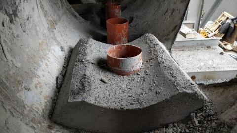
The gas ducts transition section from the header to the destruction furnace – the monolithic refractory concrete.
- The anchors of refractory concrete fixing are welded before the formwork installation.
- A 200 mm diameter polypropylene pipe is used as a fixed formwork for the gas ducts holes formation. (When concreting the furnace roof, the pipe length is selected taking into account the thickness of the refractory concrete layer in the header). The exceeding pipe length is cut after casting sequences are filled.
- The formwork for the transition section is made of 3 mm thick metal, and the formwork cover is made of 1 mm thick metal to allow the formation of casting sequence circular surface.
- After formwork installation, the refractory concrete is laid and the cover is fixed until the concrete is set and its strength develops. Then the formwork is dismantled and used later for casting sequences of all bottom transition sections (to the thermal destruction chamber).
- The formwork is installed and refractory is concreted at single casting sequence, so that the internal parts of the formwork (stiffeners) can be disassembled without damaging the refractory concrete.
The gas ducts transition section from the header to the cyclone furnace – the monolithic refractory concrete.
- Two complex areas have both vertical transition (into the destruction furnace) and horizontal transition into a cyclone furnace.
- For these areas, a single formwork was made with the possibility of concreting one large area, covering both transition sections.
- The concreting is performed through a cut-out hole in the header shell using an immersion vibrator.
- After the concrete curing and achieving the required strength, the formwork is dismantled.
Explosion relief valves – the monolithic refractory concrete.
- Before installing the formwork, the anchors of refractory concrete fixing are welded for all surface of the explosion relief valve nozzle (with pitch ~ 250 300 mm both for nozzle height and pitch circle).
- The formwork is mounted similarly to the formwork of the gas ducts transition section from the header to the destruction furnace.
- Refractory concrete is laid and after the necessary time for the concrete to set, the formwork is removed.
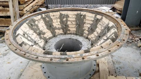
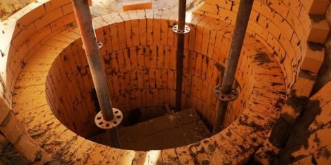
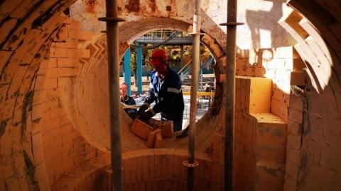
The shaped refractory (brick) laying for the entire header length is made using shaped brick (double-sided neck brick ShA-45b). The bricklaying is the ring one with the use of specially designed scaffolding for header roof refractory. The key brick is pecked/fitted in place. Once the key brick is installed, scaffolding is removed. The use of properly selected shaped bricks ensures maximum durability of the area refractory.
4. CYCLONE FURNACE
The refractory design is two-layer with the use of insulation brick and working layer brick (double-sided neck brick) — for the walls structure. For the furnace bed refractory insulation brick and working layer refractory concrete were used. The thickness of the cyclone furnace refractory is 215 mm, including: — 65 mm insulating layer, — 150 mm working layer. The stages of work are presented below:
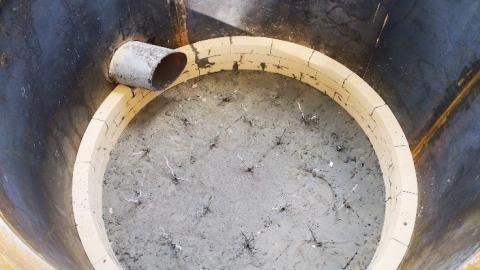
The cyclone furnace bottom – brick ShTU-1.3 No. 5 was used as an insulating layer, monolithic refractory concrete was used for the working layer.
- Insulation brick (65 mm thick) using masonry mortar based on MSh-28 mortal and a chemical hardener is laid on a previously cleaned metal surface of the furnace bottom. The brick was fitted to the furnace body vertical shell as closely as possible by its cutting.
- The refractory working layer (150 mm thickness) concreting is one-stage for the entire bottom area.
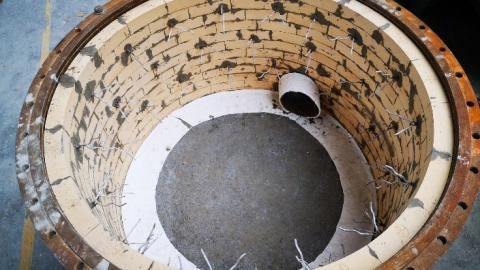
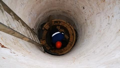
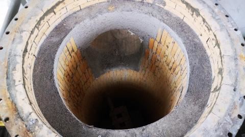
The cyclone furnace vertical section refractory – is a pre-formed refractory/brick (insulation and refractory). The furnace diameter is 1,600 mm, the height is 6,570 mm.
- Insulation brick is manufactured according to individual drawings for the cyclone furnace shell diameter specially. As a result, the bricks closely fit to the furnace body without brick cutting and pecking which accelerates the refractory work in general.
- The insulation bricklaying is bound together, for the entire height of the cyclone furnace.
- The working layer refractory combines two shaped bricks types (double-sided neck brick — ShA-45a, ShA-45b), allowing the perfectly round shape with corresponding diameter.
- The brick layout was carried out in advance, at the design stage, which reduced the refractory work time (avoiding the brick pecking, etc.).
- The working layer bricklaying is ring, with the brick step between rings (bricklaying rows bounding).
- During the furnace walls masonry a gas duct section was build up from the bottom header to the cyclone furnace, in order to avoid the gas flow from the newly installed furnace extension and also from the furnace bottom header, respectively.
- For the working layer refractory of transition section from the bottom exhaust gas duct to the cyclone furnace chimney the insulation bricks and refractory concrete are used.
The cyclone furnace horizontal gas ducts (burners location) and the gas ducts transition section from the top header to the cyclone furnace — a combined refractory with the use of insulation, refractory bricks, and monolithic refractory (concrete). The use of these refractories is due to the complexity of refractory transition sections, such as: gas ducts entrance from the top header to the cyclone furnace, the burners gas ducts entrance to the cyclone furnace. Two-layer refractory — 65 mm insulating layer is made using ShTU-1.3 curved brick, the working layer is 150 mm — refractory shaped brick (double-sided neck brick) and refractory concrete. The refractory total thickness is 215 mm. The stages of work are presented below:
Cyclone furnace burner gas ducts (2 pcs):
- For the entire gas duct circumference insulating layer the bound together curved insulating brick is used.
- The gas duct roof refractory is installed using the specially made scaffolding, including the bearing capacity of the masonry mortar and curved bricks bound together.
- Two types of shaped bricks (double-sided neck brick — ShA-45a, ShA-45b) are used for working layer allowing the perfectly round shape for burners gas ducts.
- The brick of the working layer is installed (from the side of the junction of the top header gas ducts) prior to the transition section concreting.
- On the opposite side the bricklaying reaches the height allowing the masonry without scaffolding.
- After transition section concreting (top header gas duct entrance), the rest of working layer bricks are laid with scaffolding. After installing the key bricks, the scaffolding is removed.
- Brick laying of the working layer is carried out by rings.
Top header and cyclone furnace burners gas duct joint: — monolithic refractory concrete (for two gas ducts).
- Before installing the formwork, the anchors of refractory concrete fixing are welded, as well as the insulation layer of curved bricks ShTU-1.3 is installed.
- The formwork is manufactured and installed.
- The concreting is performed through a cut-out hole in the gas duct shell using an immersion vibrator.
- After the concrete curing and achieving the required strength, the formwork is dismantled.
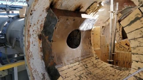
The burners gas ducts and cyclone furnace joint area is made of monolithic refractory concrete. The difficulty is due to the joint of relatively large diameters, with large area of the vertical and horizontal masonry interfacing. You can peck and cut brick for interface masonry, but this interface surface complexity inevitably entails brick undersize, negatively impacting refractory strength in general. As a result, we concluded that the use of monolithic refractory in this area is preferred.
- The formwork was manufactured and anchors were installed according to previously described procedures.
- To avoid cutting the brick and adjusting it to the overall height of the cyclone furnace masonry, a concrete belt was installed over the entire refractory cross section with the simultaneous creation of burners gas duct arch for the joint of gas duct and cyclone furnace. This belt provides the additional structural strength to cyclone furnace top cover joining.
5. END AND TOP COVERS (HEADER AND CYCLONIC FURNACE)
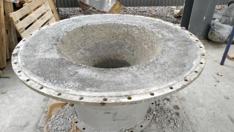
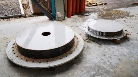
All covers refractory design is similar that’s why this topic is presented in the same section. The working layer is made of refractory concrete, the stages of work are shown below:
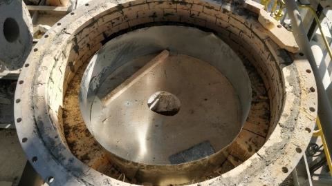
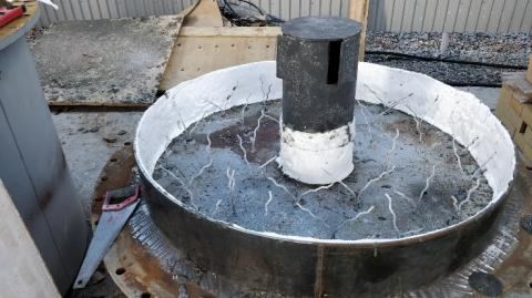
End covers of the top header (2 pcs) – 150 mm thick single-layer refractory.
- Before the refractory installing, a permanent formwork was made and installed — 6 mm thick rolled metal band ring of certain diameter, welded to the cover body.
- After the formwork installing, the anchoring was restored, with ~ 130 mm anchor height and ~ 9 pcs2 density.
- Before concrete installing, the formwork is cemented with blanket insulating material to form an expansion joint.
- The concrete is casted in one stage using immersion vibrator or manually.
End covers (2 pcs) and the top cover of the cyclone furnace – two layer refractory of 215 mm total thickness. The latter includes 65 mm of KTP-65 kaolin plate insulating layer and 150 mm monolithic refractory concrete working layer. The use of a two-layer refractory is due to the high temperature in the cyclone furnace — up to 1,200 °C.
- Permanent metal formwork installation, anchoring restoration, expansion joint installation are performed in accordance with the procedure described above.
- For the insulation layer the kaolin plate is cut and with its pieces the inter anchor space is filled. The joints of the plate fragments are filled with masonry mortar.
- The working layer of monolithic refractory concrete is installed after the mounting of insulation layer.
6. INSTALLATION OF FURNACE EXTENSION, HEADER COVERS AND CYCLONE FURNACE
Furnace extension installation:
- Prior to installation of thermal destruction furnace extension, the refractory of transition section between gas duct and bottom furnace header of the destruction furnace was restored.
- The surface of the brick at the flange junction, before connecting the gas duct to the vertical part of the furnace extension, was glued over with the blanket material using masonry mortar.
- The furnace extension was mounted by the installer Korifey LLC.
- As a sealing material for horizontal joints of the furnace extension (conical and cylindrical parts of the furnace extension), the ~ 20–25 mm thick blanket insulating material was used. Its working temperature range reaches 1,250 °C.
Installation of header covers and cyclone furnace:
- Before installation of all covers, the 6 mm thick insulating blanket seal was installed.
- After installing the flange seal an adhesive solution is applied to the flange surface of the equipment with excess (or on the surface of the previously installed seal) so that when the caps are tightened, the excess of this adhesive solution will come out
- After equipment commissioning (during start-up), with heating this adhesive solution is fully set, ensuring maximum sealing of the equipment.
- In order to provide thermal expansion of the refractory and equipment metal structure, in the area of the cover and the main refractory junction the ~ 15 mm expansion joints are installed and filled during cover mounting with 38 mm thick heat insulating material (glued to the end surface of the main refractory). When tightening the covers bolting, this insulating material is compressed more than twice, thereby ensuring maximum sealing while maintaining the possibility of thermal expansion of the refractory and steel structure.
- This principle of sealing is similar for all covers, including end and top covers of the cyclone furnace of thermal destruction furnace.
Installation of the bottom header end cover:
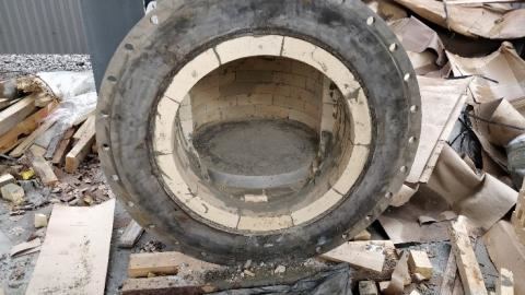
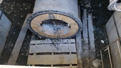
- During dismantling, the back cover of the bottom header was opened to inspect the technical condition of the bottom header refractory.
- Accordingly, before installing the cover, the refractory of this area was restored (cut brick ShA-10 of width equal to the thickness of the dismantled refractory ~ 100–120 mm was used.).
- The masonry mortar was prepared for bricklaying with MSh-28 aluminosilicate mortal and chemically active hardener.
- After masonry finishing a 20 mm thick insulating blanket was installed outside for additional insulation and compensation for possible refractory heat expansion.
- After finishing the refractory, a metal cover was bolted with adhesive solution application as a seal.
PROJECT SUMMARY:
Upon completion of all refractory works and equipment installation, it can be concluded that the complexity of this project is very high. To implement this project, all types of refractory were used with both pre-formed ones (bricks) and monolithic refractory concrete, as well as the entire auxiliary scope of works necessary for their installation was performed. A large number of various surfaces interfacing, the need to manufacture individual formwork and tooling, installation of horizontal, vertical and ceiling formwork, the use of combined solutions, all this makes the project unique and maximally complex. Despite this the project was successfully performed by Wellons.Ru LLC in a short time, ahead of schedule and with high quality. The key factors of this project successful implementation are following:
- proprietary detailed engineering;
- refractory direct management and supervising at the customer’s production site;
- close cooperation with Borovichskiy zavod ogneuporov JSC (Borovichi Refractories Plant) — products made by individual drawings reduced the refractory work period; as well as the use of the most modern refractory materials and their installation technology, the choice of SintezMontazh LLC as a subcontractor for refractory work, which has qualified, trained and certified personnel with a permit to work at Voronezhsintezkauchuk JSC facilities, as well as the entire set of necessary equipment.
